363-206-305
Maintenance Description
9-26
Issue 3 June 2000
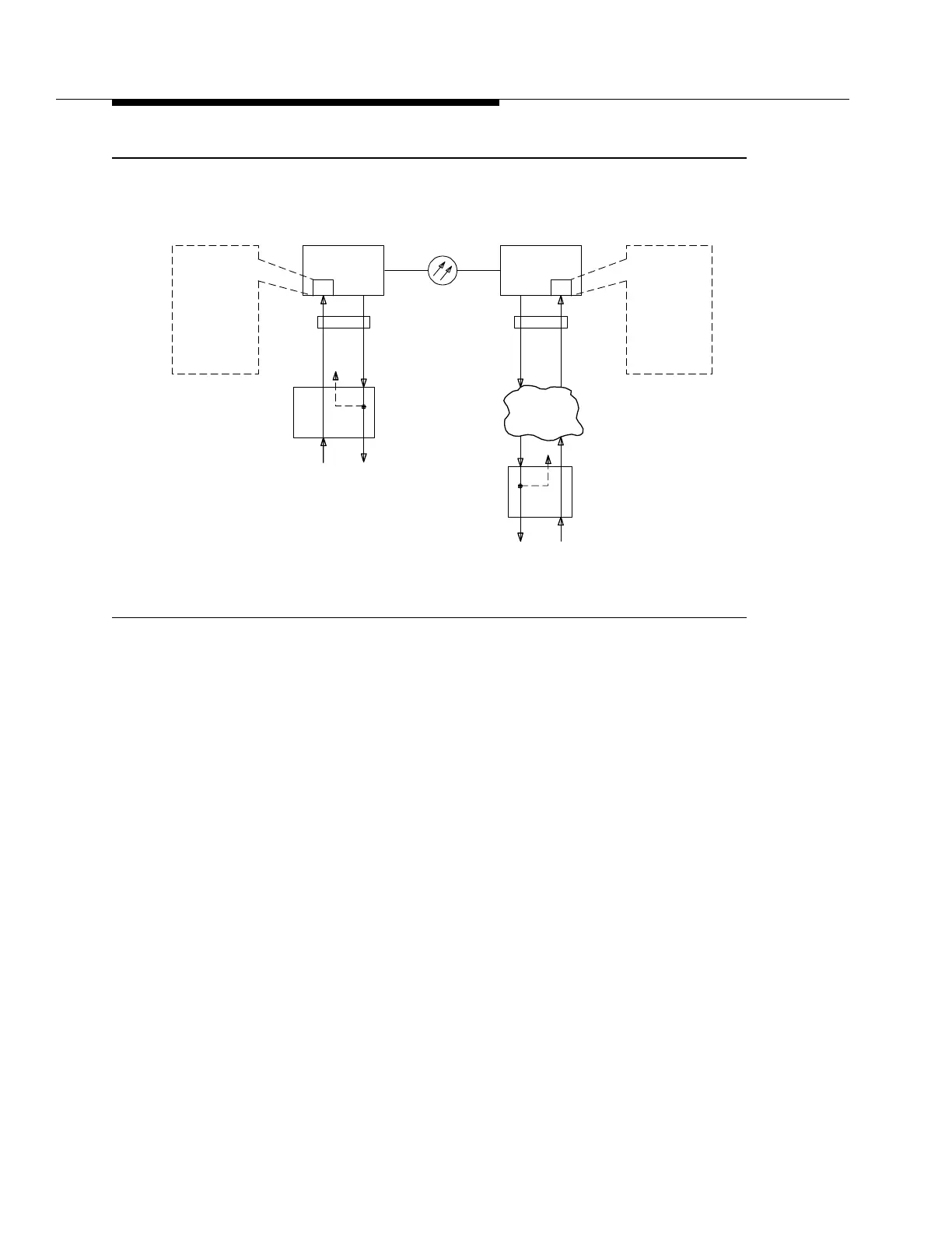
Figure 9-10. DDM-2000 Multiplexer DS1 Path Performance Monitoring
From these messages, the DDM-2000 Multiplexer can determine and report the
end-to-end error performance of the entire DS1 link
as seen by the customer
.
These parameters, listed in Table 9-1, are thresholded and reported to indicate
degraded performance. The counts are retrieved using the
rtrv-pm-t1
command to determine if the service is operating within tariffed limits.
Application of the DS1 performance monitoring feature for tariffed service
verification is shown in Figure 9-10. Here an ANSI T1.403 ESF format DS1
service carried between points A and Z, using a DDM-2000 system and
terminated at the customer's premises with channel service units (CSUs). At the
"A" end, the received error performance (Z - A) is detected and written by the
customer's CSU onto the outgoing (A - Z) ESF data link, as shown by the dashed
lines, as a performance report message (PRM). The DS1PM circuit pack
interfacing the A end reads the incoming DS1 signal's PRM (received from the
customer's premises) and reports the Z - A performance. Likewise, the OC-3
system interfacing the Z end reports the A - Z performance by reading the PRM
from the customer's "Z" CSU. By reviewing the data from each OC-3 system, the
service provider can determine the complete end-to-end performance (A - Z and Z
- A) of the customer's service.
DS1 PATH
PERFORMANCE
MONITOR
Z-A
Performance
Report
A-B
Performance
Report
DDM-2000
M
POINT B
POINT A
CSU
POINT C
Network
OC-1
Legend:
CSU - Channel Service Unit
PRM - Performance Report Message
Z-A
PRM
DSX-1
DDM-2000
M
DSX-1
DS1 PATH
MONITOR
PERFORMANCE
A-Z
Performance
Report
Z-C
Performance
Report
POINT Z
CSU
A-Z
PRM