363-206-305
Technical Specifications
10-36
Issue 3 June 2000
OC-3 Optical Interface Mixing
10
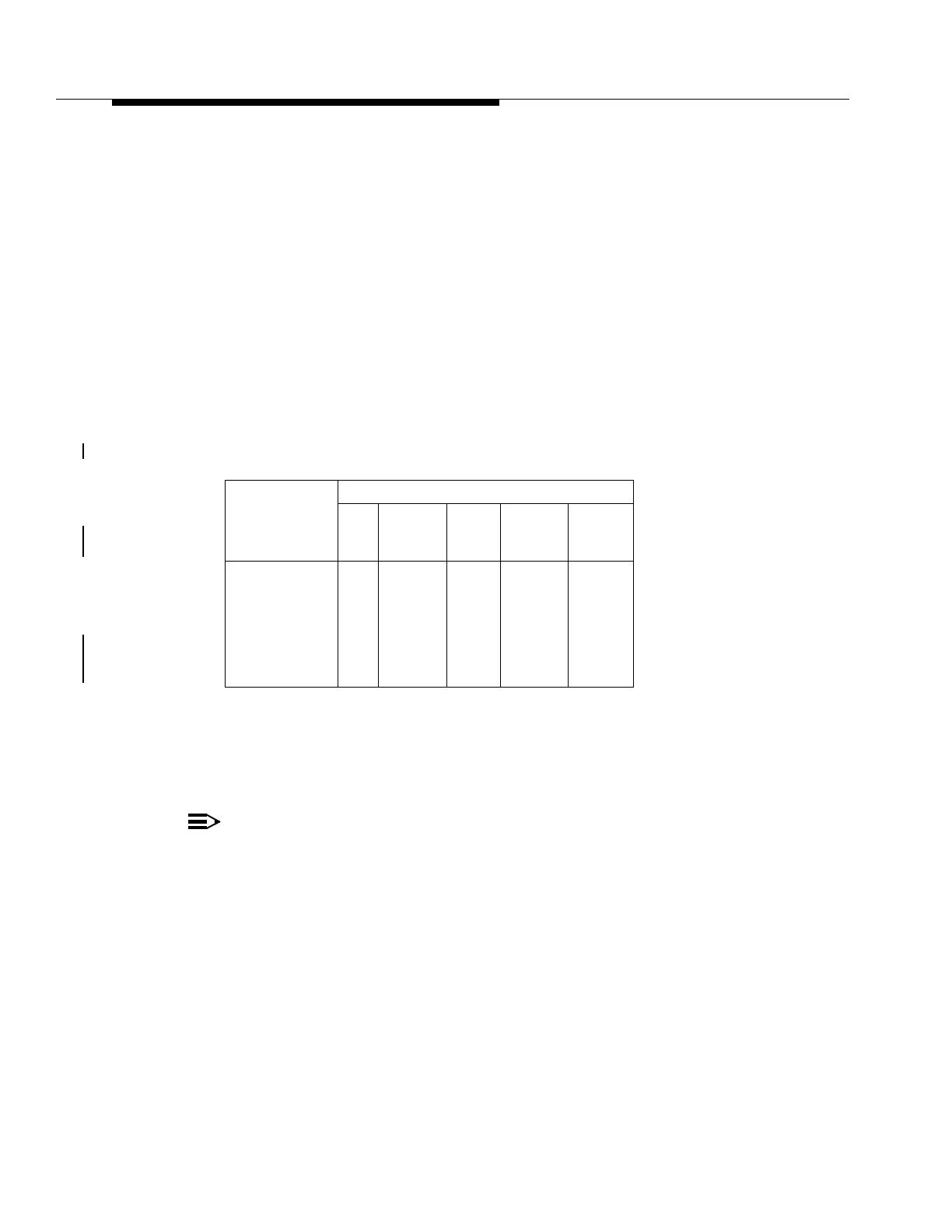
Mixing different OC-3 rate OLIUs at opposite ends of an optical link is often
necessary for technical reasons or for convenience. The following information will
aid in planning and engineering optical links having different types of OC-3 rate
OLIUs at each end of the fiber. Table 10-17 details the minimum link budget
necessary for each pairing of OC-3 rate OLIUs.
To use Table 10-17, locate the number at the intersection of the transmitter/
receiver pair of interest. This number is the minimum attenuation necessary for
proper operation of that transmitter/receiver pair. The link must have at least this
much attenuation either from fiber loss, splice loss, connector loss, external
attenuators, or a combination of these, or the receiver will be overdriven and the
link will not operate properly.
Table 10-17. OC-3 Rate OLIU Mixes - Minimum Link Budgets (dB)
Note that the minimum link budget is not always symmetrical. A transmitter/
receiver pair may have one minimum link budget in one direction and another in
the opposite direction. Be careful of this asymmetry when planning and
engineering a link having mixed OLIUs.
NOTE:
When using universal optical buildout attenuators for OLIUs equipped with
Universal Optical Connectors (for example, 28G-U and 22D-U), the buildout
must have the same type fiber on both sides, that is, single-mode to single-
mode or multimode to multimode. The buildout must also match the mode
of the fiber. Therefore, when a single-mode jumper is used, the buildout
would be on the transmit side (OUT) of the OLIU and when a multimode
jumper is used, the buildout would be on the receive side (IN) of the OLIU.
When using in-line attenuators for non-U OLIUs, place the attenuator in the
bay frame PANDUIT. Make sure that the mode type of the attenuator
matches the mode of the fiber to ensure proper attenuation.
Transmitter
Receiver
22F
22F-U/
22F2-U 22G-U
22G2-U/
22G3-U/
22G4-U
28G-U/
28G2-U
22F
22F-U/22F2-U
22G-U
22G2-U/
22G3-U/
22G4-U
28G-U/28G2-U
0.0
0.0
7.0
7.0
7.0
0.0
0.0
0.0
0.0
0.0
0.0
0.0
7.0
7.0
7.0
0.0
0.0
0.0
0.0
0.0
0.0
0.0
0.0
0.0
0.0