31
SC100/200 Series Users Manual EM-6337-B Rev.15
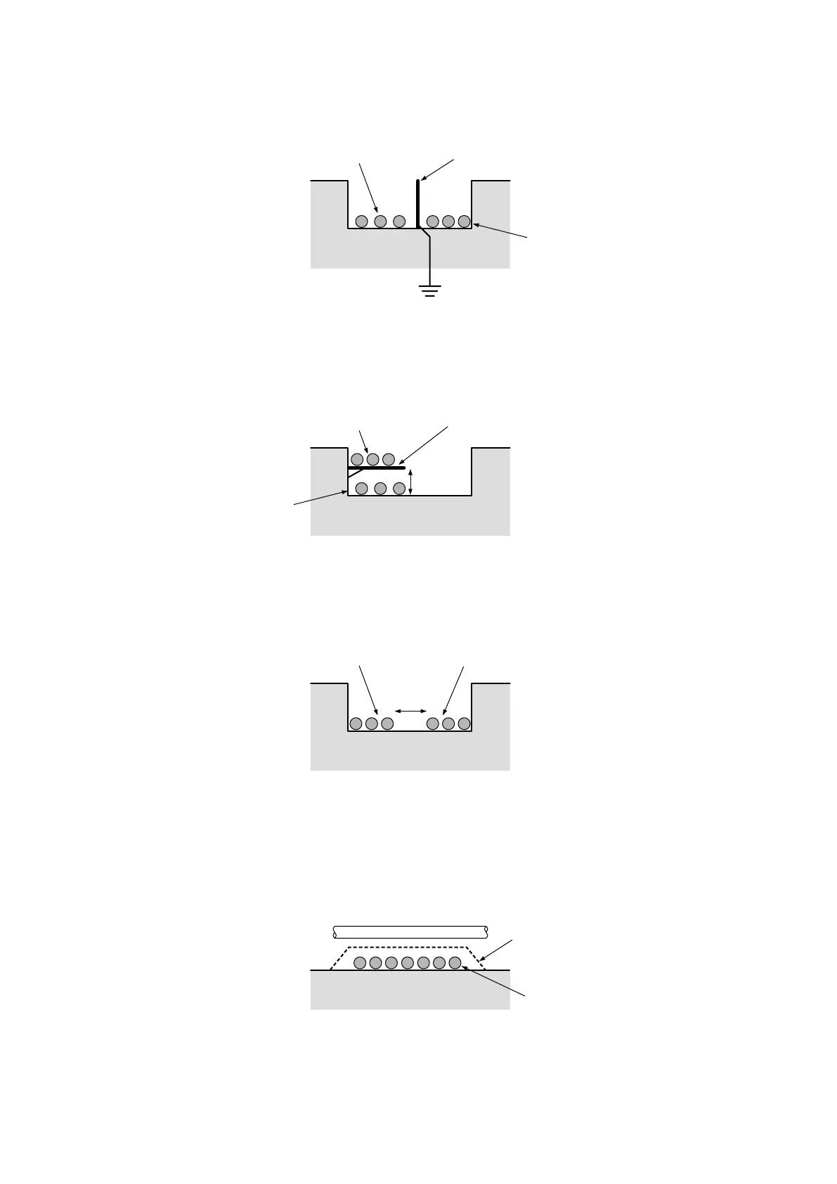
4.7.2. CABLE INSTALLATION
Separator Installation
Use a separator between Modbus-RTU cables and power supply/other signal cables installed in one pit or duct.
Cable Rack Installation
For using a cable rack, leave a space of 15 cm minimum from power supply/other signal cables as shown in the gure
below. Separate Modbus-RTU cables by 60 cm or more if the current owing to the power supply is 10 A or more.
Separation Space between Cables
If a separator is not used, leave a space of 15 cm minimum from power supply/other signal cables as shown in the drawing
below. Keep Modbus-RTU cables away by 60 cm or more if the current owing to the power supply is 10 A or more.
Right-angled Cross Wiring
When the Modbus-RTU line is crossing over the power supply/other signal line, lay the cables at a right angle.
If the Modbus-RTU cables are not shielded, it is recommended to cover the power supply/other signal cables in the intersec-
tional point with metal plate of 1.6 mm minimum thickness, as represented with dotted line in the drawing.
Separator
Power Cables
Modbus-RTU Cables
Grounding (resistance 10 ohms or less)
Cable Rack
Power Cables
Other Signal Cables
Modbus-RTU Cables
15 cm min.
Modbus-RTU Cables Power Cables, Other Signal Cables
15 cm min.
Modbus-RTU Cables
Thickness
16 mm min.
Power Cables
Other Siganl Cables