104
SC100/200 Series Users Manual EM-6337-B Rev.15
11.4. HOW TO REPLACE THE CONTROL MODULE
Before replacing a failed control module, transfer its complete setting to the replacement module.
CAUTION !
Replacing is conducted by a personnel qualied by M-System.
Refer to Section 11.3.1. STATUS TRANSITION DIAGRAM regarding control operations to shift to/from the backup mode.
(1) Switch to the backup mode.
The front LEDs start turning on and blinking according to the Mv 2 output level. If the Controller has been automatically
switched to the backup mode, the LEDs are already functioning.
The Mv 2 output can be controlled by the front control buttons with the help of LEDs in this state.
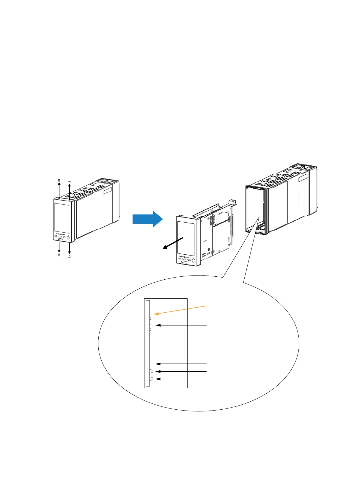
(2) Unfasten four screws at the top and bottom of the front part (See the gure below at the left) and extract the control mod-
ule.
The Mv 2 output can be controlled by the relevant buttons and LEDs on the backup module at this point.
MV output setting indicators
Backup Module
MV value (DOWN) button
Acceleration button
MV value (UP) button
Seen from the front