82
SC100/200 Series Users Manual EM-6337-B Rev.15
7.2. FIELD INPUT SETTING
In this section, conguration items related to external connection of the Controller are explained.
7.2.1. PROCESS & ANALOG INPUT SETTING
For process input (Pv 1, Pv 2), choose among 26 input types. Be aware that the terminal connection differs depending upon
input types. The factory default setting is “3: 1 to 5 V”.
GROUP [04] EXTENSION TERMINAL 1 “▲” marked data modiable in PROGRAM mode.
ITEM MDFY DATA INPUT DEFAULT SETTING CONTENTS
36
▲
MM TP1: 3 Pv 1 input type
[MM: input type No.] 12: S 19: Pt100 (JIS ‘97, IEC)
0: -10-10 V 6: K 13: C 20: Pt100 (JIS ‘89)
1: -1-1 V 7: E 14: N 21: JPt100 (JIS ‘89)
2: 0-10 V 8: J 15: U 22: Pt50 (JIS ‘81)
3: 1-5 V 9: T 16: L 23: Ni100
4: 0-1 V 10: B 17: P 24: MS
5: 4-20 mA 11: R 18: PR 25: DS
(Set ITEM37...39 for Pv 1 input type 6...23)
37
▲
-272.0 – 3000.0 HT1: 1000 Pv 1 upper range temperature
38
▲
-272.0 – 3000.0 LT1: .0 Pv 1 lower range temperature
39
▲
0, 1 CJ1: 1 Pv 1 cold junction compensation (0: Without, 1: With)
40
▲
MM TP2: 3 Pv 2 input type
[MM: input type No.] 12: S 19: Pt100 (JIS ‘97, IEC)
0: -10-10 V 6: K 13: C 20: Pt100 (JIS ‘89)
1: -1-1 V 7: E 14: N 21: JPt100 (JIS ‘89)
2: 0-10 V 8: J 15: U 22: Pt50 (JIS ‘81)
3: 1-5 V 9: T 16: L 23: Ni100
4: 0-1 V 10: B 17: P 24: MS
5: 4-20 mA 11: R 18: PR 25: DS
(Set ITEM41...43 for Pv 1 input type 6...23)
41
▲
-272.0 – 3000.0 HT2: 1000 Pv 2 upper range temperature
42
▲
-272.0 – 3000.0 LT2: .0 Pv 2 lower range temperature
43
▲
0, 1 CJ2: 1 Pv 2 cold junction compensation (0: Without, 1: With)
7.2.2. DISCRETE & PULSE INPUT SETTING
Discrete inputs (Di) and pulse inputs (Pi) share the same terminal. Channels set to ‘0’ function as discrete input; those set to
‘1’ function as pulse input. The factory default setting is ‘00000,’ all channels are assigned as discrete input.
GROUP [05] EXTENSION TERMINAL 2 “▲” marked data modiable in PROGRAM mode.
ITEM MDFY DATA INPUT DEFAULT SETTING CONTENTS
31
▲
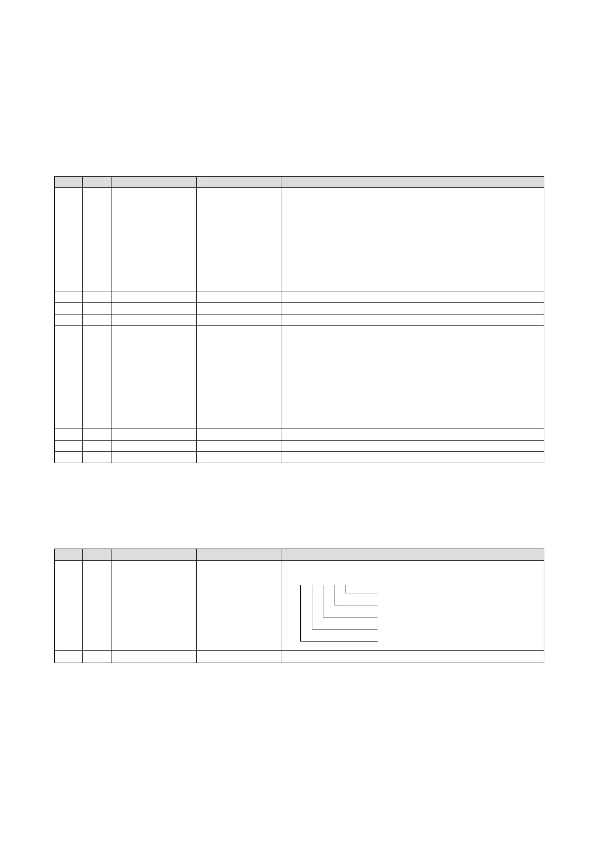
NNNNN PD:00000 Di/Pi selection (0 = Di, 1 = Pi)
NNNNN
Di 1 / Pi 1
Di 2 / Pi 2
Di 3 / Pi 3
Di 4 / Pi 4
Di 5 / Pi 5
52
▲
N PD6: 1 Di/Pi selection (0 = Di, 1 = Pi)
Caution !
When a channel is set to pulse input, ladder sequences employing the channel as discrete input do not function.