91
SC100/200 Series Users Manual EM-6337-B Rev.15
9.2. AUTO-TUNING OPERATIONS
With all auto-tuning parameters set, choose ‘AT : Run Auto-tuning.’ If the selected reference tuning point (CV) value is greater
than the setpoint (SP), a message for caution appears on the screen to warn a possible damage to the control system.
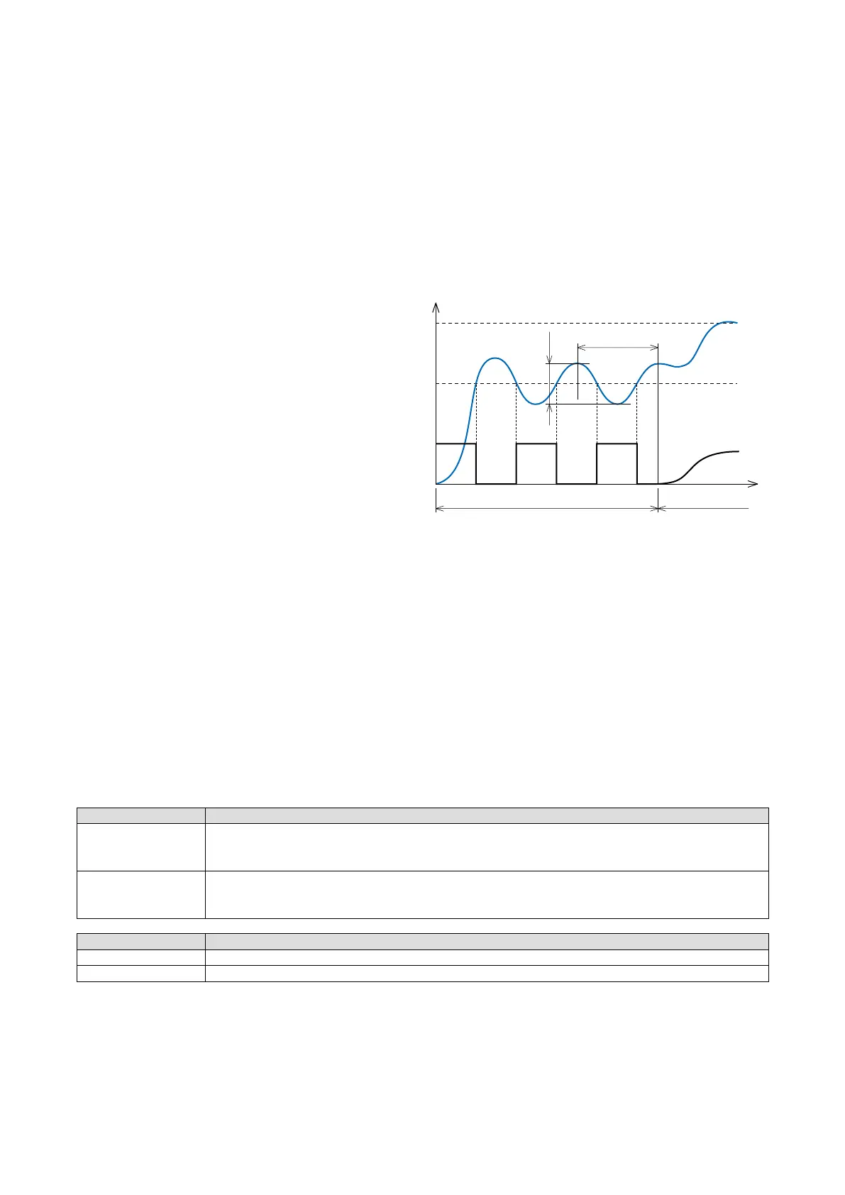
Control output (MV) is changed in a step between 100% and 0%. PV amplitude (Kcp) and frequency (Tcp) are measured
to calculate appropriate PID parameters. When MV high limit (MH) is set to a value lower than 100% and/or low limit (ML)
to one higher than 0%, MH and/or ML values are used for oscillation. Fix MV at 0% when the control action (DR) is set to
‘1 : Reverse (MV decreases with increasing PV);’ or at 100% when it is set to ‘0 : Direct,’ and wait until PV is stable enough
before starting auto-tuning procedure.
The following example of the Controller operation is applied to reverse control action.
1) Blue AUTO indicator starts blinking. MV is switched to 100% and then to 0% when PV crosses across CV.
2) MV is then again switched to 100% when PV crosses
across CV the second time. These cycles are re-
peated for twice.
3) Amplitude (Kcp) and frequency (Tcp) of the reacting
PV waveform as in the gure to the right are meas-
ured.
4) P, I and D parameters are obtained from the following
formulae using Kcp and Tcp values. The a, b and c
values depend upon optimization and control action
settings.
Proportional gain: K = a Kcp
(Proportional band : PB = 100% / K)
Integral time: TI = b Tcp
Derivative time: TD = c Tcp
5) Store the calculated parameters and go back to nor-
mal PID control mode. Green AUTO indicator is turned on.
When the auto-tuning procedure is completed abnormally as explained in the following, ‘MI : Fixed MV’ at error value is ap-
plied as MV.
• When PV goes over PV high limit or below PV low limit.
• When the procedure does not complete before preset time out (TO) is elapsed.
• When ‘AT : Stop Auto-tuning’ is selected (a message for caution appears on the screen).
9.3. OPTIMIZATION & CONTROL ACTION
OPTIMIZATION DESCRIPTION
Process change (= Constant-value control)
PID parameters are calculated so to suit PV signal change (disturbance). Choose this option for single loop
control and for primary loop control in a cascade control loop.
Setpoint change (= Follow-up control)
PID parameters are calculated so to suit SP signal change.
Choose this option for secondary loop control in a cascade control loop.
OPERATION MODE DESCRIPTION
PID P, I and D parameters
PI P and I parameters
SP
CV
PV
MV
100%100% 100%
0% 0%
Tcp
Kcp
Auto-tuning in progress PID control
t
The above figure shows operation with reverse control action.
MV cycles are inverted with direct action.
Wait to start the procedure until PV is stabilized.