89
SC100/200 Series Users Manual EM-6337-B Rev.15
8. COMMUNICATING WITH THE SFEW3E PROGRAM
8.1. GENERAL DESCRIPTION
The Loop Conguration Builder Software (model: SFEW3E) is used to upload and download the function block data.
Refer to the Users Manual for the SFEW3E for detailed descriptions.
8.2. CONNECTING THE CONTROLLER TO PC
Connect the Controller to PC in order to communicate with the SFEW3E.
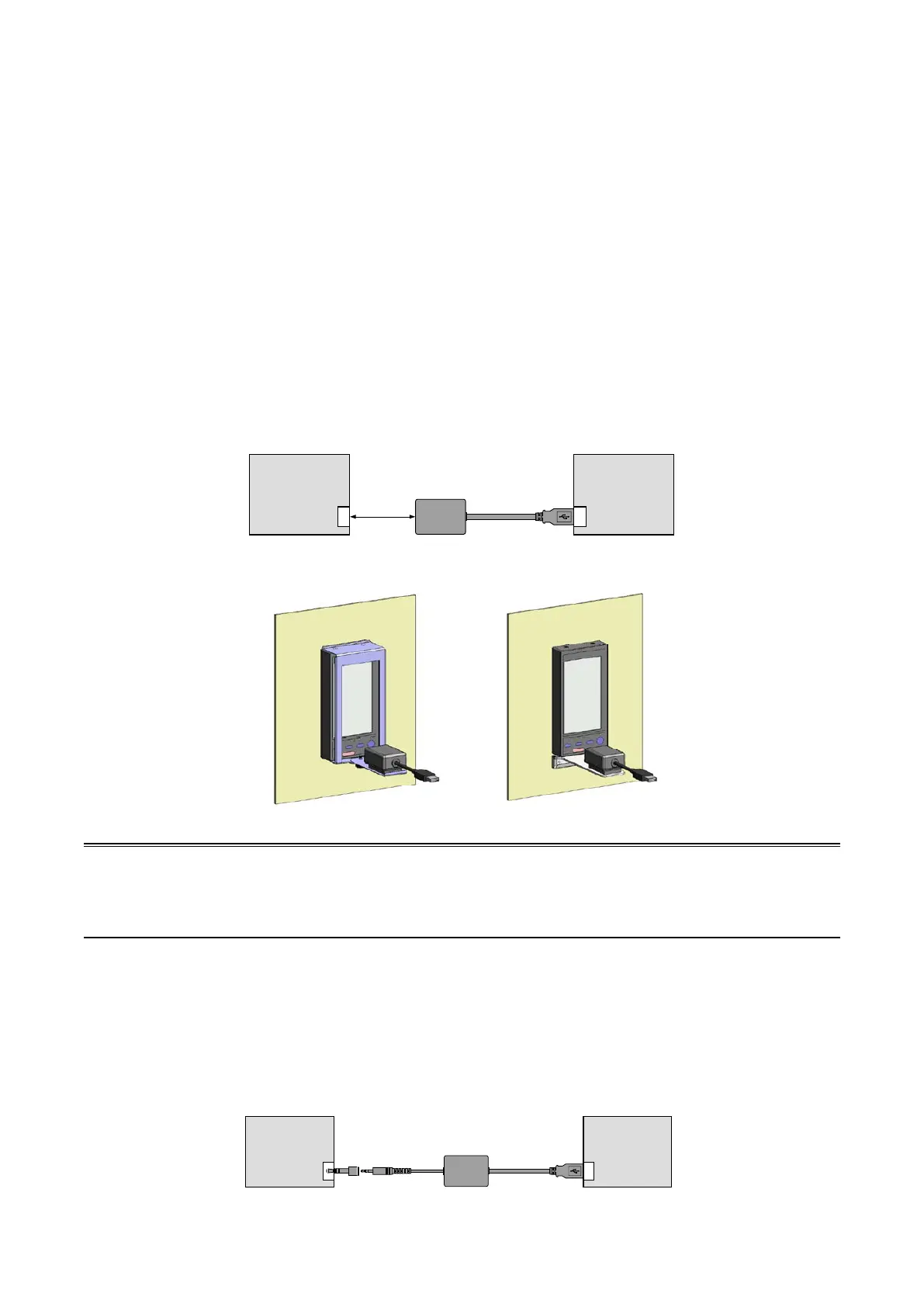
8.2.1. INFRARED COMMUNICATION TYPE
1) Install the SFEW3E program and driver for Infrared Communication Adaptor device (model: COP-IRDA) to the PC and
connect the COP-IRDA to its USB port.
2) Start up the SFEW3E and set the COM port number assigned to the USB in the initial setting.
3) Set the infrared port in the direct line to face the COP-IRDA’s send/receive window, within the maximum distance of 0.2
meter.
4) Go to Engineering View and choose Conguration > 01 : Cong mode > 02 : SFEW. The front monitoring LED starts
blinking slowly to indicate the ready state. Refer to Section 6.3.1.4. CONFIG MODE to operate the Controller.
PC
SFEW3E
Controller
COP-IRDA
USB portInfrared port
Max. 0.2 m
N144 (two-part type) Holder L Type Holder
Using Holders
Caution
(1) Only one Controller module can communicate with the SFEW3E or SCCFG when multiple modules are mounted side
by side. Detecting more than one module at once in the communication mode will result in error.
(2) The Controller may not be able to establish normal communication in an environment present with noise from invert-
ers.
8.2.2. STEREO JACK TYPE
1) Install the SFEW3E program and driver for PC Congurator cable (model: COP-US) to the PC and connect the COP-US
to its USB port.
2) Start up the SFEW3E and set the COM port number assigned to the USB in the initial setting.
3) Connect the COP-US to the connector adaptor and after this, to the Controller’s jack port.
4) Go to Engineering View and choose Conguration > 01 : Cong mode > 02 : SFEW. The front monitoring LED starts
blinking slowly to indicate the ready state. Refer to Section 6.3.1.4. CONFIG MODE to operate the Controller.
PC
SFEW3E
Controller
COP-US
USB portStereo jack
Connector
adapter