37
SC100/200 Series Users Manual EM-6337-B Rev.15
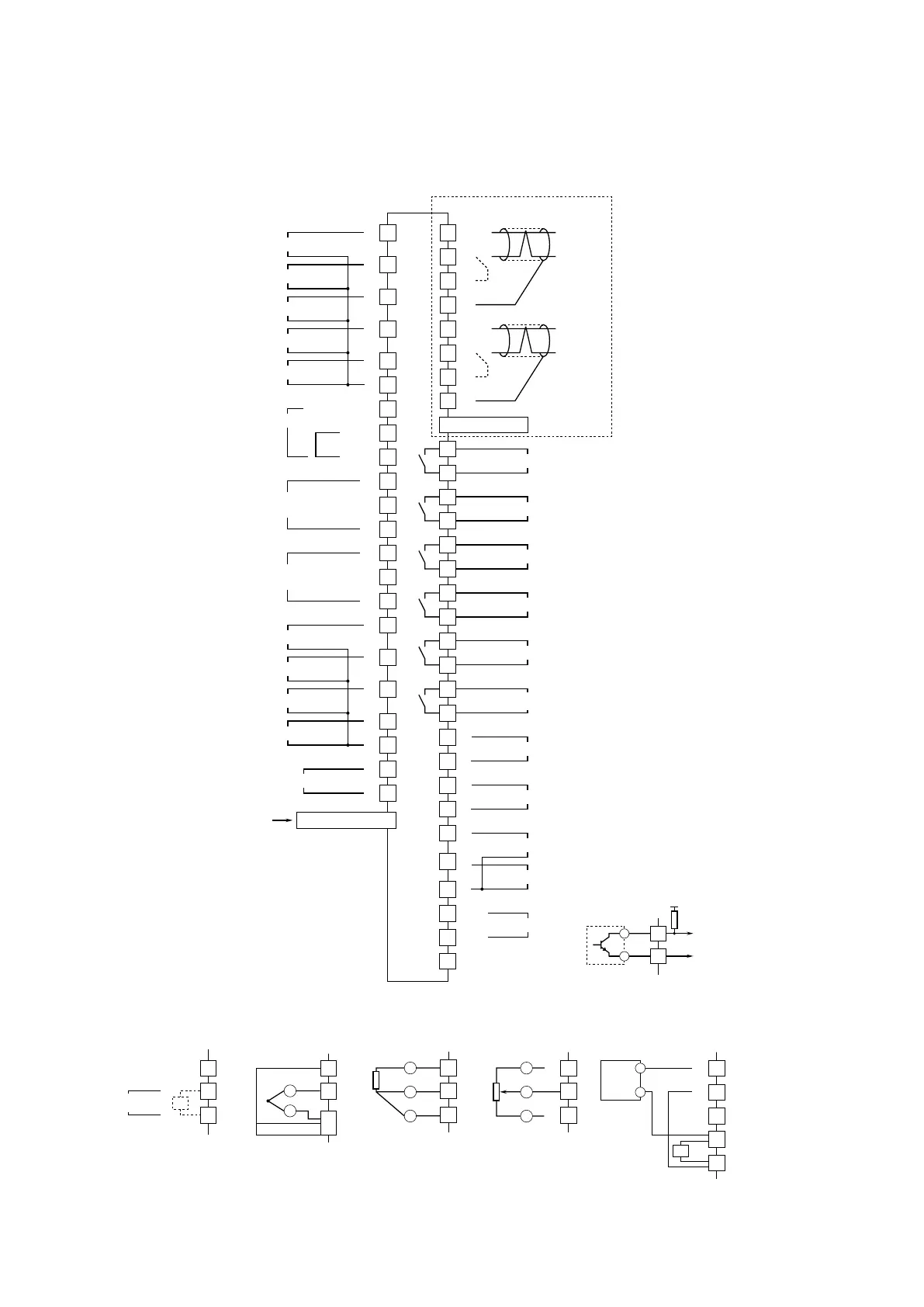
4.9. CONNECTION DIAGRAM
■ SC100/200
Note: In order to improve EMC performance, bond the FG terminal to ground.
Caution: FG terminal is NOT a protective conductor terminal.
34
35
36
37
38
39
31
33
32
42
A1
B1
C1
44
43
45
47
46
A2
B2
C2
48
49
50
51
52
16
17
18
19
20
21
22
23
24
25
10
11
3
+
4
–
+
–
+
+
U(+)
V(–)
FG
–
+
+
+
+
–
+
+
+
+
+
–
5
6
7
8
9
12
13
26
Do 1
Do 2
Do 3
Do 4
Do 5
Di 1 / Pi 1
Di 2 / Pi 2
Di 4 / Pi 4
Di 3 / Pi 3
Di 5 / Pi 5
Di 6 / Pi 6
Pv 1
UNIVERSAL INPUT
Pv 2
UNIVERSAL INPUT
Ai 1
Ai 2
Ai 3
Ai 4
POWER
Ao 2
Ao 1
Mv 2
Mv 1
SENSOR EXC
INPUT
COM
Do 6
RUN CONTACT
+
–
2
1
28
41
40
27
14
15
Jumper*
1
Shielded Twisted-pair Cable
To Other
NestBus
Devices
SHLD
Modbus/TCP
RJ-45 CONNECTOR
T4
T1
T2
T3
+
–
Jumper*
2
Shielded Twisted-pair Cable
To Other
Modbus-RTU
Devices
SHLD
T4
T1
T2
T3
*3. Connect input resistor module (model: REM4) for current input.
*4. Connect CJC sensor for thermocouple input.
*5. Connect input resistor module (model: REM4).
*1. Close across the terminals 27 – 28 when the unit is located at the end of a transmission line (= no cross-wiring).
*2. Close across the terminals 14 – 15 when the unit is located at the end of a transmission line (= no cross-wiring).
■ UNIVERSAL INPUT CONNECTION E.G.
A
B
T/C
CJC SENSOR
C
*3
*4
*5
A
B
C
R
29
30
2-Wire
XMTR
+
–
+
–
+
–
PC CONFIGURATOR/
BUILDER SOFTWARE
Infrared Port / Jack
+
–
Dry contact
1 or 2kΩ
A
B
C
R
+
–
VOLT / CURRENT
INPUT
A
B
B
RTD
A
B
C
A
B
C
3
2
1
POTENTIOMETER
max.
min.
+
–
29
30
+
–
2-WIRE TRANSMITTER
+12V
SC200 External Interface
■ DISCRETE INPUT PULSE
INPUT CONNECTION E.G.: