67
SC100/200 Series Users Manual EM-6337-B Rev.15
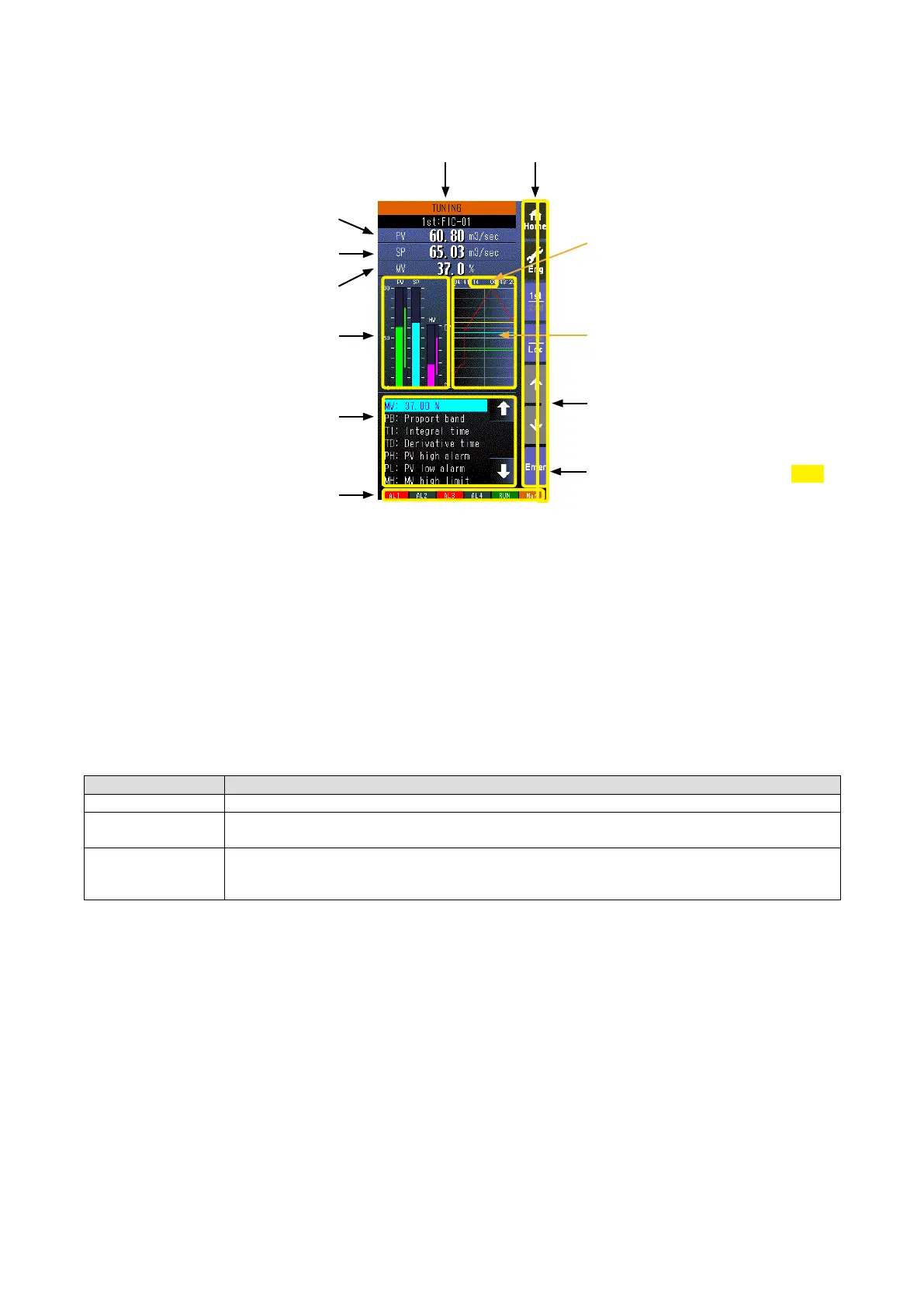
6.3.3. TUNING (AUTO-TUNING) VIEW
6.3.3.1. SCREEN COMPONENTS
Alarm Indicator
Red bar blinks during error.
* Indicators
Operation Buttons
PV Digital Display
SP Digital Display
MV Digital Display
Tag No.
Bargraphs
Tuning Parameters List
Trend Graph
Status
Stop or P (Pause)
• 100 sample data is plotted on the trend graph.
• The trend graph is reset (cleared) and restarted when:
- When the power supply is turned on with ‘Trend recording’ set to ‘Start.’
- When ‘Trend recording’ setting is changed from ‘Stop’ to ‘Start.’
- When ‘Storing interval’ setting is changed.
- When ‘Trend channel’ setting is changed.
- When setting is initialized. (Refer to: 6.3.1.35. INITIALIZE)
- When setting is changed and applied by PC congurator software (model: SCCFG).
* Indicators
INDICATOR EXPLANATIONS
AL1 to AL4 Background color turns red during alarm.
RUN / STOP RUN: Green in normal conditions; Amber in an abnormality.
STOP: Grey when the Controller operation is stopped; Red when the memory is failed.
Auto / Man Auto: Green Auto indicator turns on.
Man: Orange Man indicator turns on.
The lamp indicates the status of the loop being on the screen.
PRG mode indicator
Yellow bar blinks during program mode
1.50