79
SC100/200 Series Users Manual EM-6337-B Rev.15
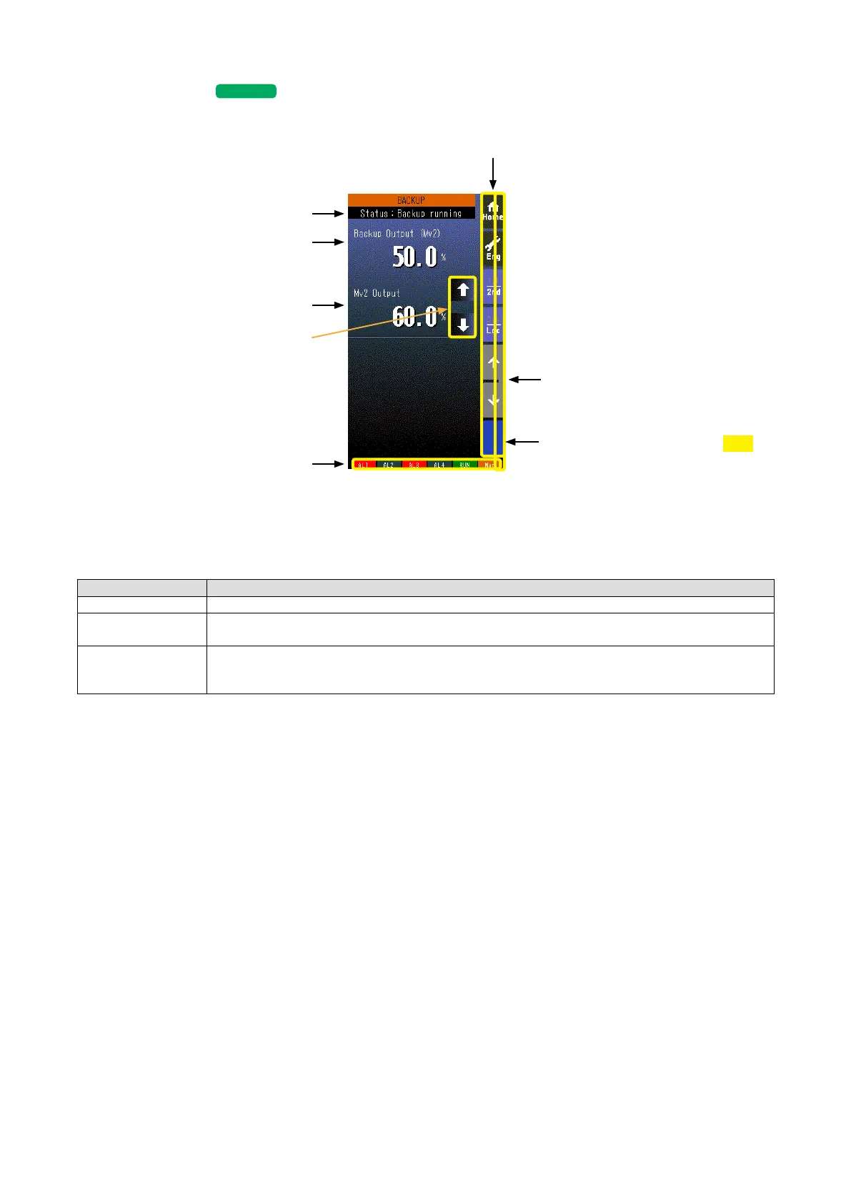
6.3.6. BACKUP VIEW
SC110/210
6.3.6.1. SCREEN COMPONENTS
Alarm Indicator
Red bar blinks during error.
* Indicators
Operation Buttons
Status Display
Backup Module Mv 2 Output
Control Module Mv 2 Output
MV Control Buttons appear when
the recovery mode is set to ‘Manual
Tracking’ and the backup status is
at ‘Backup Running.’
PRG mode indicator
Yellow bar blinks during program mode
1.50
• Status display shows either of the following: Normal / Standby backup / Backup running / Backup error.
• Mv 2 is represented in percentage with one decimal place.
* Indicators
INDICATOR EXPLANATIONS
AL1 to AL4 Background color turns red during alarm.
RUN / STOP RUN: Green in normal conditions; Amber in an abnormality.
STOP: Grey when the Controller operation is stopped; Red when the memory is failed.
Auto / Man Auto: Green Auto indicator turns on.
Man: Orange Man indicator turns on.
The lamp indicates the status of the loop being on the screen.