95
SC100/200 Series Users Manual EM-6337-B Rev.15
11. BACKUP (MANUAL LOADING)
SC110/210
If the Controller module fails, it can be replaced while the Mv 2 output is maintained.
Backup/manual loading is applicable to Mv 2 only.
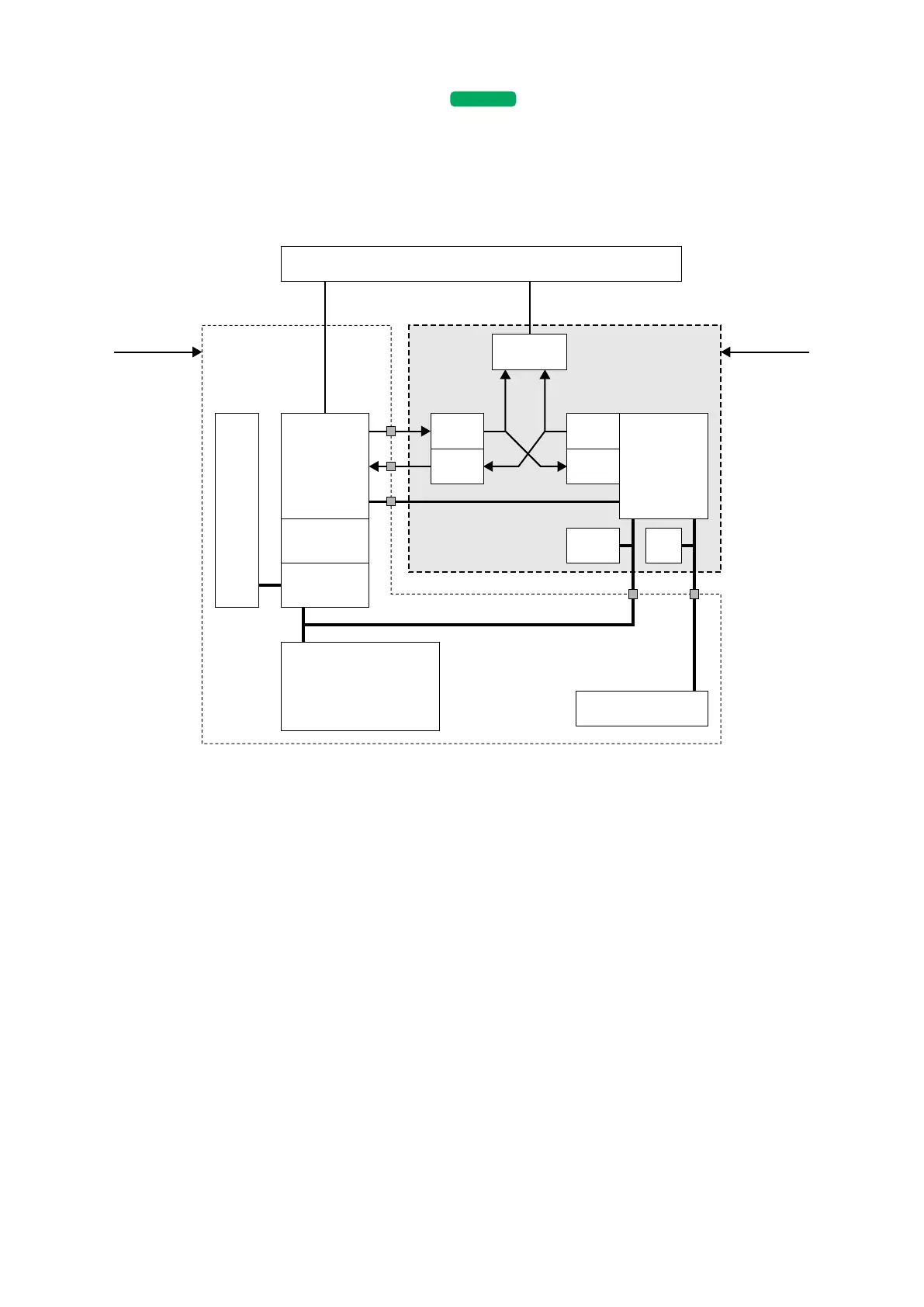
11.1. HARDWARE CONSTRUCTION
• Controller module and Backup module maintain monitoring each other’s status.
• The front LED indicators for Mv 2 are connected to that of the backup module; while the front UP/DOWN control buttons are
connected in parallel to both modules.
• Optionally (specied when ordering), the backup module could have its own power supply circuit independent from that of
the controller module.
• The backup module takes in the feedback signal (analog) of the control module output to track it for its own output.
• In normal conditions, the Mv 2 selector SW is set to the control module.
• When the control is switched to the backup module either manually or automatically, the Mv 2 selector SW is set to the
backup module.
• Transition of output level in the switching is smooth as the backup module has been continuously tracking the control mod-
ule output.
• The control mode is set to Manual and manual loading for Mv 2 using the front control buttons is available in this mode.
• RUN contact is turned OFF (open) in backup state, which may differ from RUN value in 6.3.4. REALTIME I/O MONITOR-
ING VIEW.
I/O CPU Backup CPULCD
Control CPU
DAC
Selector SW
Terminal Block
ADC
DAC
ADC
LED
Front LEDs (5)
Buttons
Display CPU
Front Control Buttons
• MV value DOWN
• Acceleration
• MV value UP
• AUTO/MAN selector
Power Supply 2Power Supply 1
Backup Module(Main) Control Module
RUN Contact
Connector
Communication
Output
Feedback
Mv2