40
SC100/200 Series Users Manual EM-6337-B Rev.15
5. DEFAULT LOOP CONFIGURATION
5.1. GENERAL DESCRIPTIONS
The Controller is designed to suit with a wide variety of applications using two PID function blocks together with numerous
computational functions.
The factory default programming enables the Controller to function as basic PID controller.
The explanation for the usage with the factory default settings is described below.
Parameters can be changed with the touch panel.
5.2. EX-FACTORY SETTING
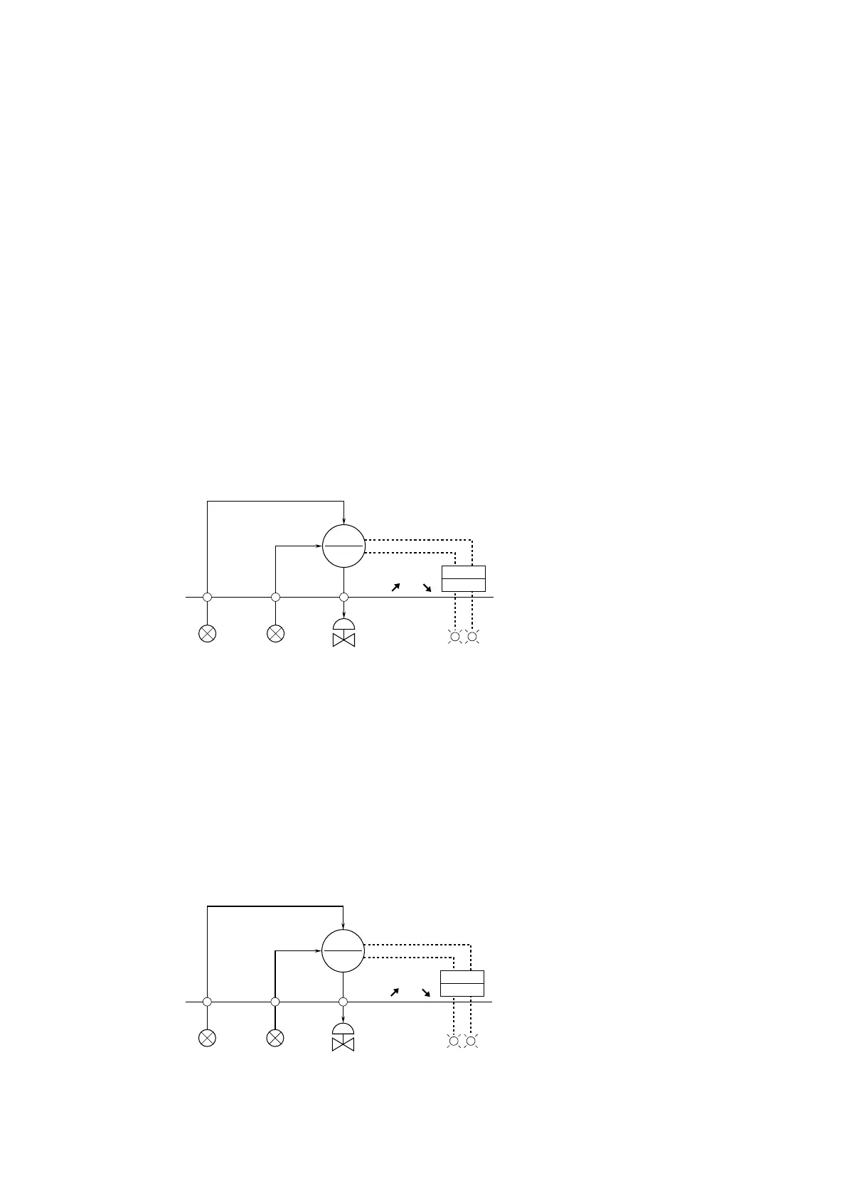
• Loop 1
Basic PID is preset.
Measured input (Pv 1) is provided to PID block. MV output from the PID block is connected to the external Mv 1 terminal.
Analog input (Ai 1) is assigned to CAS terminal of the PID block. The setting method ‘0’ (LOCAL) is set, therefore SP value
can be changed only on the front panel control.
When CASCADE/LOCAL setting mode ‘1’ is selected, cascade control with Ai 1 value is available. High and low alarms for
Pv 1 are displayed at AL1 and AL2 lamp on the LCD.
*1. Factory default
Note: Use the Loop Conguration Builder Software (model: SFEW3E) for loop conguration.
• Loop 2
Basic PID is preset.
Measured input (Pv 2) is provided to PID block. MV output from the PID block is connected to the external Mv 2 terminal.
Analog input (Ai 2) is assigned to CAS terminal of the PID block. The setting method ‘0’ (LOCAL) is set, therefore SP value
can be changed only on the front panel control.
When CASCADE/LOCAL setting mode ‘1’ is selected, cascade control with Ai 2 value is available. High and low alarms for
Pv 2 are displayed at AL3 and AL4 lamp on the LCD.
*1. Factory default
Note: Use the Loop Conguration Builder Software (model: SFEW3E) for the loops conguration.
CAS
PID
G02
1 – 5 V DC
P : 100%
I : No integral action
D : No derivative action
Mv 1Pv 1Ai 1
1 – 5 V DC
*1. Factory default setting
Use Loop Configuration Builder Software (model: SFEW2)
to modify setting.
H
L
AL2AL1
SEQ
G81
4 – 20 mA DC
■ LOOP 1
Reverse Action
(PV /MV )
*
1
*
1
CAS
PID
G03
1 – 5 V DC
P : 100%
I : No integral action
D : No derivative action
Mv 2Pv 2Ai 2
1 – 5 V DC
H
L
AL4AL3
SEQ
G81
4 – 20 mA DC
*
1
*
1
Reverse Action
(PV /MV )
CAS
PID
G02
1 – 5 V DC
P : 100%
I : No integral action
D : No derivative action
Mv 1Pv 1Ai 1
1 – 5 V DC
*1. Factory default setting
Use Loop Configuration Builder Software (model: SFEW2)
to modify setting.
H
L
AL2AL1
SEQ
G81
4 – 20 mA DC
■ LOOP 1
■ LOOP 2
Reverse Action
(PV /MV )
*
1
*
1
CAS
PID
G03
1 – 5 V DC
P : 100%
I : No integral action
D : No derivative action
Mv 2Pv 2Ai 2
1 – 5 V DC
H
L
AL4AL3
SEQ
G81
4 – 20 mA DC
*
1
*
1
Reverse Action
(PV /MV )