50
SC100/200 Series Users Manual EM-6337-B Rev.15
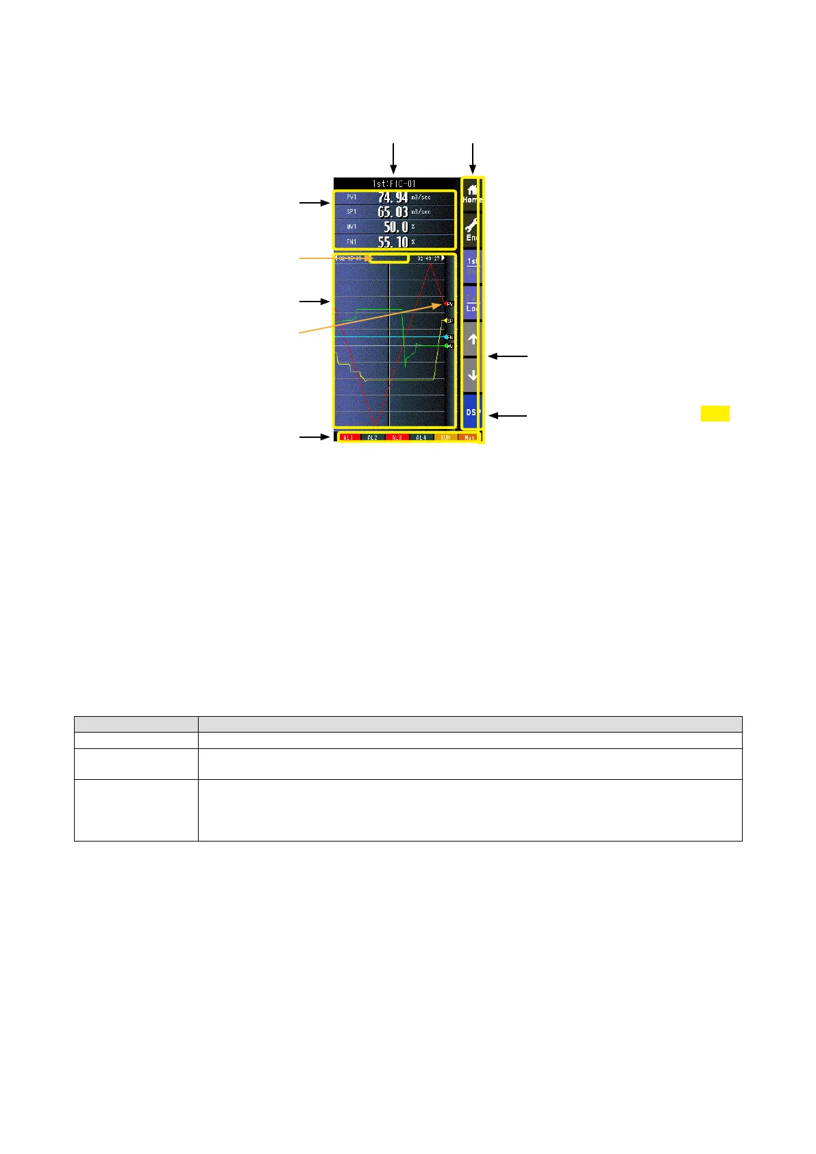
6.2.4. SHORT TREND VIEW
6.2.4.1. SCREEN COMPONENTS
Alarm Indicator
Red bar blinks during error.
Tag No.
Status
Stop or Pause
Trend Graph
* Indicators
Operation Buttons
Digital Display Field
Shows parameters specied by
‘Trend channel’ setting.
Triangles show the position of
present values. The pointers
track latest values even when
plotting is paused.
PRG mode indicator
Yellow bar blinks during program mode
1.50
• Pressing on [1st/2nd] button switches between the primary and secondary loops.
• 200 samples are plotted on the chart.
• The graph operation is linked with that on Tuning view.
• Graph plotting is reset to restart in either of the following conditions:
- When the power supply is turned on with ‘Trend recording’ set to ‘Start.’
- When ‘Trend recording’ setting is changed from ‘Stop’ to ‘Start.’
- When ‘Storing interval’ setting is changed.
- When ‘Trend channel’ setting is changed.
- When setting is initialized. (Refer to: 6.3.1.35. INITIALIZE)
- When setting is changed and applied by PC congurator software (model: SCCFG).
* Indicators
INDICATOR EXPLANATIONS
AL1 to AL4 Background color turns red during alarm.
RUN / STOP RUN: Green in normal conditions; Amber in an abnormality.
STOP: Grey when the Controller operation is stopped; Red when the memory is failed.
Auto / Man Auto: Green Auto indicator turns on.
Man: Orange Man indicator turns on.
The lamp indicates the status of the loop specied in ‘Loop display (MV/OP)’ setting.
(Refer to: 6.3.1.12. LOOP DISPLAY (MV/OP))