69
SC100/200 Series Users Manual EM-6337-B Rev.15
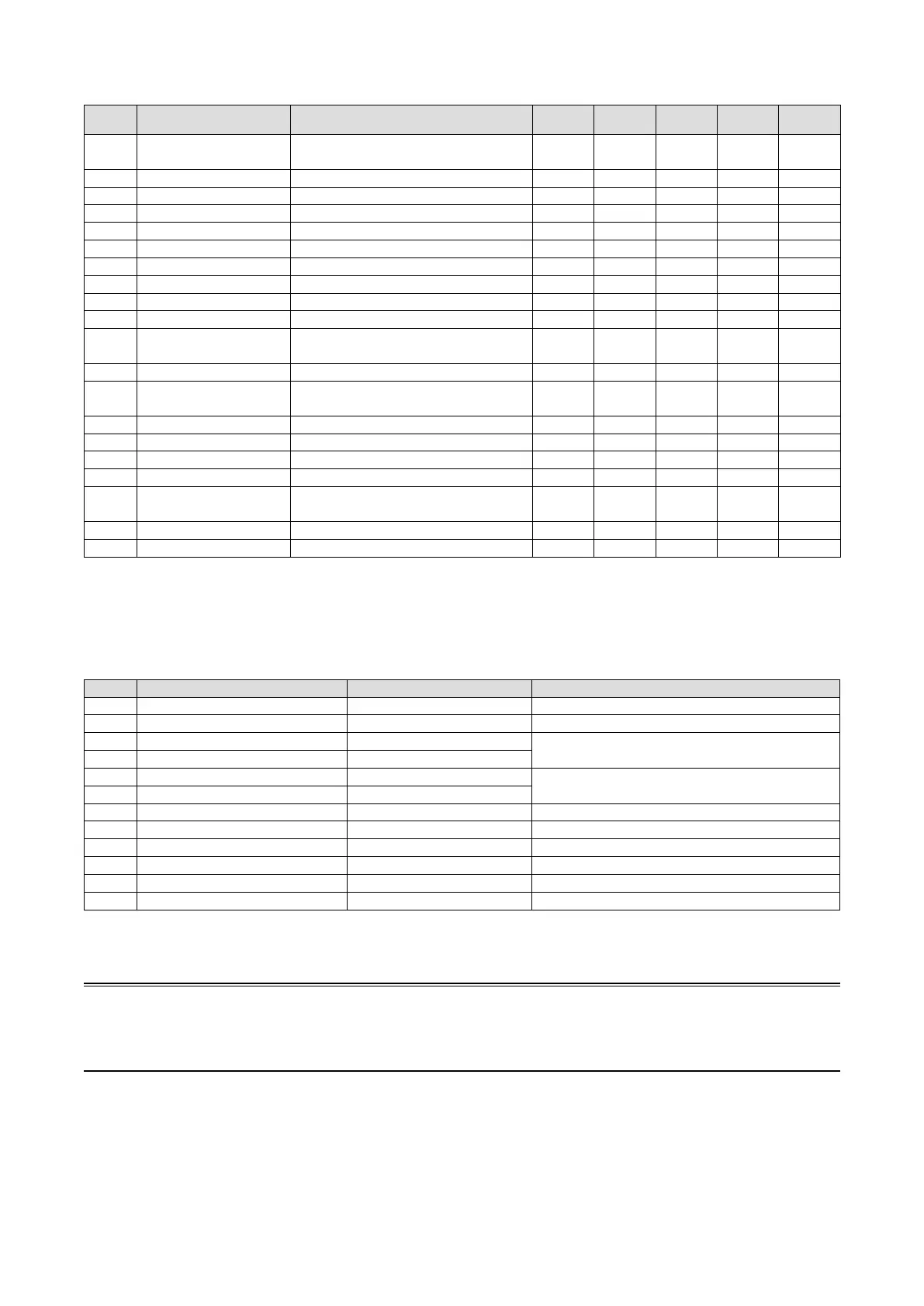
6.3.3.3. TUNING PARAMETERS
ABBR SELECTABLE RANGE CONTENTS
Basic PID
Advanced
PID
MV
Control
Ratio
Setting
Indicator
SP -15.00 to 115.00% Setpoint value (Local mode) X X ----
X
±32.000
----
MV ±115.00% Manipulated value (Man mode) X X X X ----
PB 0 to 1000% Proportional band X X ---- ---- ----
TI 0.00 to 100.00 min. Integral time (0: No integral) X X ---- ---- ----
TD 0.00 to 10.00 min. Derivative time (0: No derivative) X X ---- ---- ----
PH -15.00 to 115.00% PV alarm high limit X X ---- X X
PL -15.00 to 115.00% PV alarm low limit X X ---- X X
MH ±115.00% MV high limit X X ---- ---- ----
ML ±115.00% MV low limit X X ---- ---- ----
DL 0.00 to 115.00% Deviation alarm setpoint X X ---- ---- ----
SM
Local,
Cascade/Local
Setting mode X X ---- X ----
DR Direct, Reverse Control direction X X ---- ---- ----
DM
PV derivative,
Deviation deriv
Derivative type X X ---- ---- ----
MD Direct, Reverse MV control direction display X X X X ----
TG 10 characters Tag No. (Tag name) X X X X X
MH ±32000 Upper range in engineering unit X X ---- X X
ML ±32000 Lower range in engineering unit X X ---- X X
DP 0, 1, 2, 3, 4, 5
Decimal point position
(number of decimal places)
X X ---- X X
TU 8 characters Unit X X ---- X X
AT To Auto-tuning view X X ---- ---- ----
Note 1. SM: Ai signal can be used as SP when Cascade/Local mode is selected.
Note 2. All parameters except AT are locked during the SFEW communication mode.
Note 3. For more details, refer to SC100/200 Series Function Block List.
6.3.3.4. AUTO-TUNING PARAMETERS
ABBR SELECTABLE RANGE CONTENTS REMARKS
SP -15.00 to 115.00% Setpoint value Local mode only.
CV -15.00 to 115.00% Tuning point Default value: 50%
P1 -15.00 to 115.00% PV high limit
Auto-tuning is cancelled when PV is over the high limit
or below the low limit.
P2 -15.00 to 115.00% PV low limit
M1 ±115.00% MV high limit
MV changes in steps within MV high/low limits.
M2 ±115.00% MV low limit
MI ±115.00% Fixed MV at error MV is xed at this value at error.
TO 1 to 3200 minutes Time out period
CM Setpoint change, Process change Optimization
CA PID, PI Control action
TU To Tuning view
AT Start auto-tuning
Note 1. SP or AT is locked during the SFEW communication mode.
Note 2. Refer to Section 9. AUTO-TUNING for detailed explanations on each parameter.
Note
Rounding of fractions for engineering unit is rounding down.
Example) When engineering unit range is 0.00 to 30.00 kg and input value is 49.96 %, 14.988 is obtained by converting
to engineering unit. 14.98 is displayed by rounding down.

 Loading...