46
SC100/200 Series Users Manual EM-6337-B Rev.15
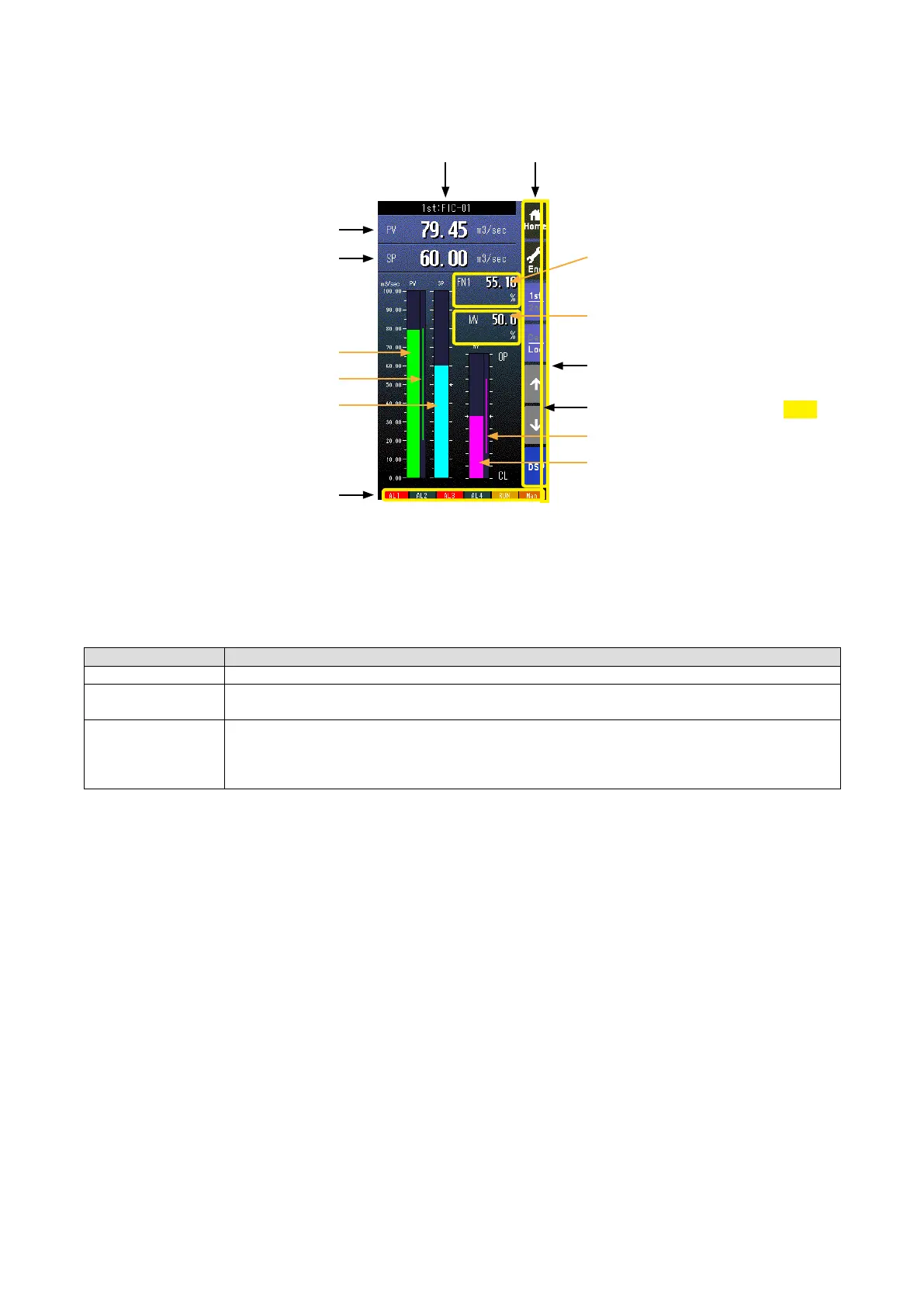
6.2.2. BARGRAPH DISPLAY VIEW
6.2.2.1. SCREEN COMPONENTS
Alarm Indicator
Red bar blinks during error.
Tag No.
SP Digital Display
PV Bargraph
PV Normal Range Indicator
SP Bargraph
* Indicators
MV Digital Display
FNx Digital Display
FN1 - FN4 switched in turn.
Skipped if not assigned.
(e.g. FN1 > FN2 > FN1)
MV Output Limit Range Indicator
MV Bargraph
Operation Buttons
PV Digital Display
• Pressing on [1st/2nd] button switches between the primary and secondary loops.
• PV and SP values are shown in engineering unit value.
• Engineering unit and % scale can be switched with PV and SP bargraphs.
* Indicators
INDICATOR EXPLANATIONS
AL1 to AL4 Background color turns red during alarm.
RUN / STOP RUN: Green in normal conditions; Amber in an abnormality.
STOP: Grey when the Controller operation is stopped; Red when the memory is failed.
Auto / Man Auto: Green Auto indicator turns on.
Man: Orange Man indicator turns on.
The lamp indicates the status of the loop specied in ‘Loop display (MV/OP)’ setting.
(Refer to: 6.3.1.12. LOOP DISPLAY (MV/OP))
PRG mode indicator
Yellow bar blinks during program mode
1.50