44
SC100/200 Series Users Manual EM-6337-B Rev.15
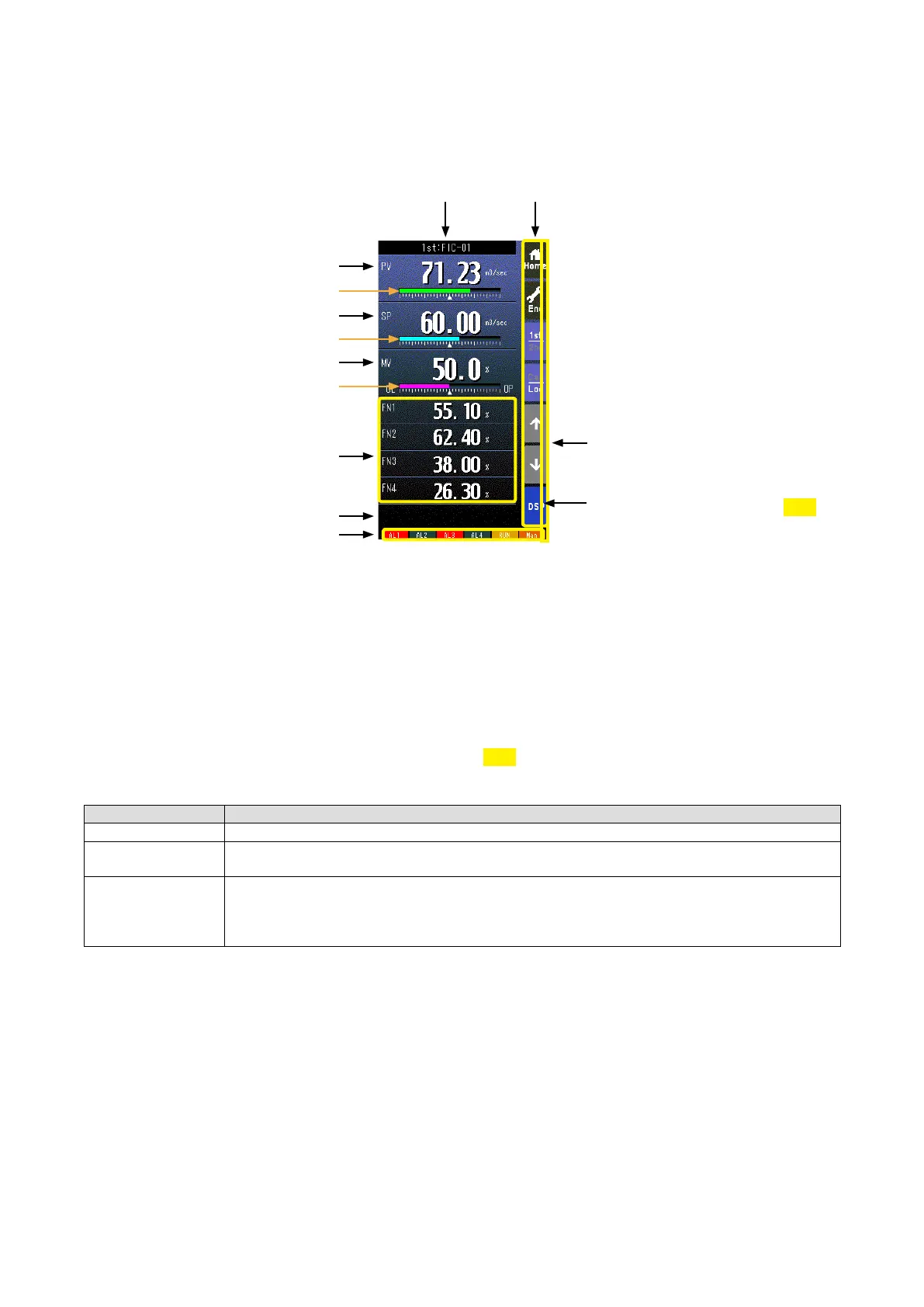
6.2. OPERATION VIEWS
6.2.1. DIGITAL DISPLAY VIEW
6.2.1.1. SCREEN COMPONENTS
Alarm Indicator
Red bar blinks during error.
* Indicators
Operation Buttons
PV Digital Display
SP Digital Display
MV Digital Display
Tag No.
MV Bargraph
FN1 to FN4 Displays
SP Bargraph
PV Bargraph
Error Message
• Pressing on ‘1st/2nd’ button switches between the primary and secondary loop.
• Bargraphs represent respective signals in percentage.
• PV and SP digital displays can be switched between engineering unit data and percentage.
• Switching is possible when ‘Select unit mode’ setting is set to ‘Selectable.’ (Refer to: 6.3.1.28. SELECT UNIT MODE)
• When error is detected, the error message is displayed on the ERROR code area.
• Refer to Appx 5. DIGITAL DISPLAY ERROR MESSAGES.
• Tag No. (FN1 to FN4) can be displayed maximum 4 characters.
1.50
* Indicators
INDICATOR EXPLANATIONS
AL1 to AL4 Background color turns red during alarm.
RUN / STOP RUN: Green in normal conditions; Amber in an abnormality.
STOP: Grey when the Controller operation is stopped; Red when the memory is failed.
Auto / Man Auto: Green Auto indicator turns on.
Man: Orange Man indicator turns on.
The lamp indicates the status of the loop specied in ‘Loop display (MV/OP)’ setting.
(Refer to: 6.3.1.12. LOOP DISPLAY (MV/OP))
PRG mode indicator
Yellow bar blinks during program mode
1.50