IMPULSE
®
•G+ & VG+ Series 4 Technical Manual
November 2020
Page 113
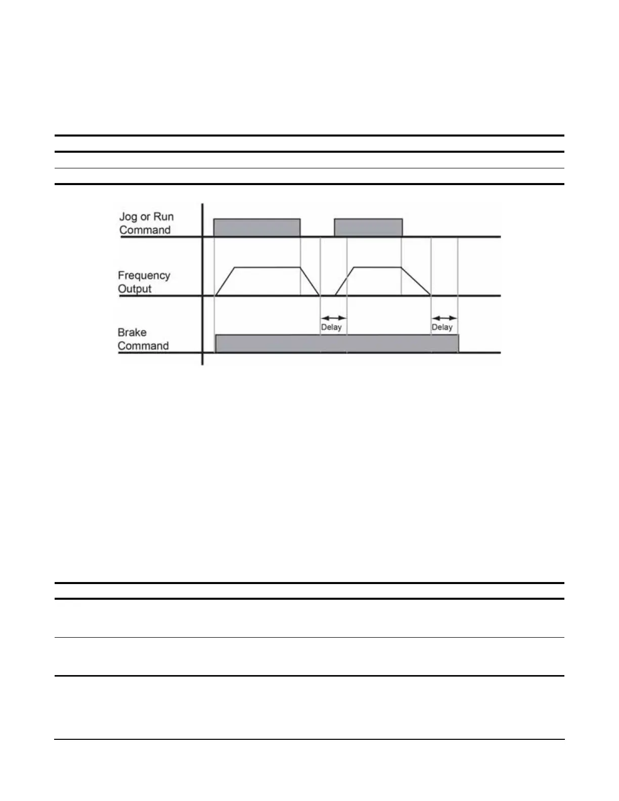
5.2.22 Brake Delay Timers
This function is used in trolley or bridge applications. It can reduce the mechanical brake wear when the operator
positions a load. This function is available only in traverse mode and B03-03 must be set to 4 (Decel With Timer).
Table 5-38: Delay Timers Parameter Settings
Figure 5-15: Brake Delay Timers
NOTE: The Jog control input is a multi-function input. It is enabled by programming H01-01–08 = 15 or 16.
5.2.23 Timer Function
• The timer function is enabled when the timer function MFDI (H01-0x = 43) and the timer function MFDO (H02-
0x = 12) are set respectively.
• The input and output serve as general purpose I/O. Chattering of sensors, switches, contactors, etc., can be
prevented by setting a delay time.
• When the timer function input ON time is longer than the value set for C12-03 (Timer function ON-Delay Time),
the timer function output turns ON.
• When the timer function input OFF time is longer than the value set for C12-04 (Timer function OFF-Delay
Time), the timer function output turns OFF.
Table 5-39: Timer Function Parameter Settings
* This function is enabled when timer function is set to MFDI/MFDO; H01-xx=43, H02-xx=12.
Parameter Display Function Range Default
C12-01 Brake Jog Delay Brake set delay time at Jog Control input. 0.0–100.0 sec 0.0
C12-02 Brake Run Delay Brake set delay time at RUN input. 0.0–100.0 sec 0.0
Parameter Display Function Range Default
C12-03* Delay-ON timer Timer function output On-delay time (dead
zone) for timer function input is set at a unit of
seconds.
0.0–3000.0 sec 0.0
C12-04* Delay-OFF timer Timer function output Off-delay time (dead
zone) for timer function input is set at a unit of
seconds.
0.0–3000.0 sec 0.0

 Loading...


