IMPULSE
®
•G+ & VG+ Series 4 Technical Manual
November 2020
Page 122
Table 5-47: ASR Tuning Parameter Settings
These parameter settings will function differently depending on the control method.
NOTE: Mechanical backlash in an application can cause secondary current (I
2
) reference variations in the motor’s
rotor. This condition can prevent the desired adjustment of ASR parameters. The output delay time
constant is used to increase the stability of the system allowing a wider setting range of ASR parameters.
5.3.4.3 Flux Vector (FLV)
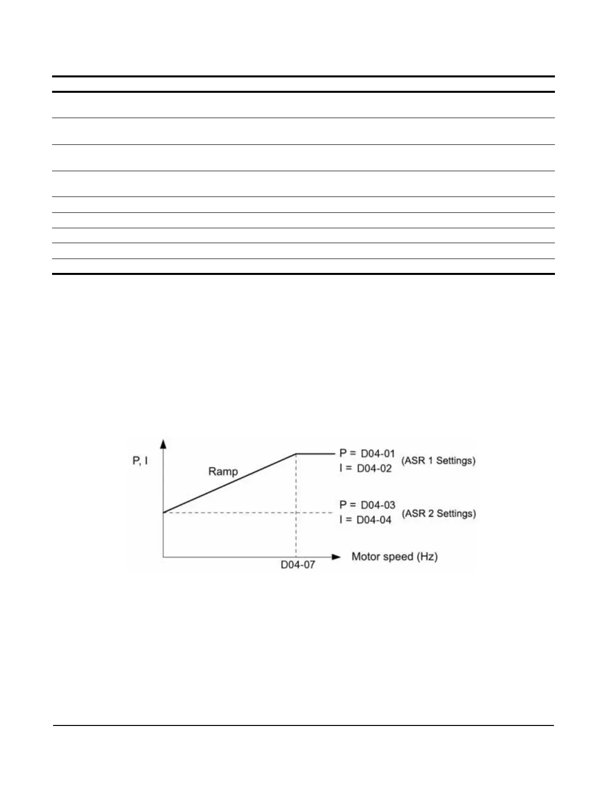
Parameters D04-03 and D04-04 define the ASR proportional gain an integral time at zero speed. The settings in
D04-01 and D04-02 are used at speeds above the setting in D04-07. D04-07 is set by default to 0.0 so D04-01 and
D04-02 are used by default over the entire speed range. However, changing D04-07 creates two levels of ASR
control settings, as shown in Figure 5-19 below.
Figure 5-19: Low-speed and High-speed Gain Settings
Parameter Display Function Range Default
D04-01 ASR P Gain 1 Sets the proportional gain of the speed control
loop (ASR).
0.00–300.00 20.00
D04-02 ASR I Time 1 Sets the integral time of the speed control loop
(ASR).
0.000–10.000 sec 0.500
D04-03 ASR P Gain 2 Sets the speed control gain 2 of the speed control
loop (ASR).
0.00–300.00 20.00
D04-04 ASR I Time 2 Sets the integral time 2 of the speed control loop
(ASR).
0.000–10.000 sec 0.500
D04-06 ASR Delay Time ASR Output Primary Delay Time. 0.000–0.500 sec 0.004
D04-07 ASR Gain SW Freq ASR Gain Switching Frequency. 0.0–150.0 Hz 0.0
D04-08 ASR I Limit ASR Integral Limit. 0–400% 400
D04-36 NLB Strt ASR I Integral Time at NLB start 0.000–30.000 0.100
D04-37 NLB Strt ASR Dly ASR Gain Delay at NLB start 0.00–2.55 0.50

 Loading...


