IMPULSE
®
•G+ & VG+ Series 4 Technical Manual
November 2020
Page 155
5.6.4 Digital Outputs—Alarm/Fault Annunciate (H02-01–03=40)
Digital Outputs—Fault Annunciate enables you to assign a set of six fault outputs to Relay Output M2/M3 and/or
Output M5/M6. In addition, you can select whether each fault output is enabled.
NOTE: Output M0/M1 can be used for Digital Outputs—Fault Annunciate; it is normally assigned to a brake
output.
Before you start to program this feature, you may find it convenient to first photocopy the “Binary-to-Hexadecimal
Conversion Worksheet” in this section. By being able to write in the worksheet’s boxes, you will find it easier to
program the feature.
Programming Digital Outputs—Fault Annunciate requires that you determine two 4-digit binary numbers and
then convert these numbers to two 1-digit hexadecimal numbers. You enter the hexadecimal numbers when you
program the VFD.
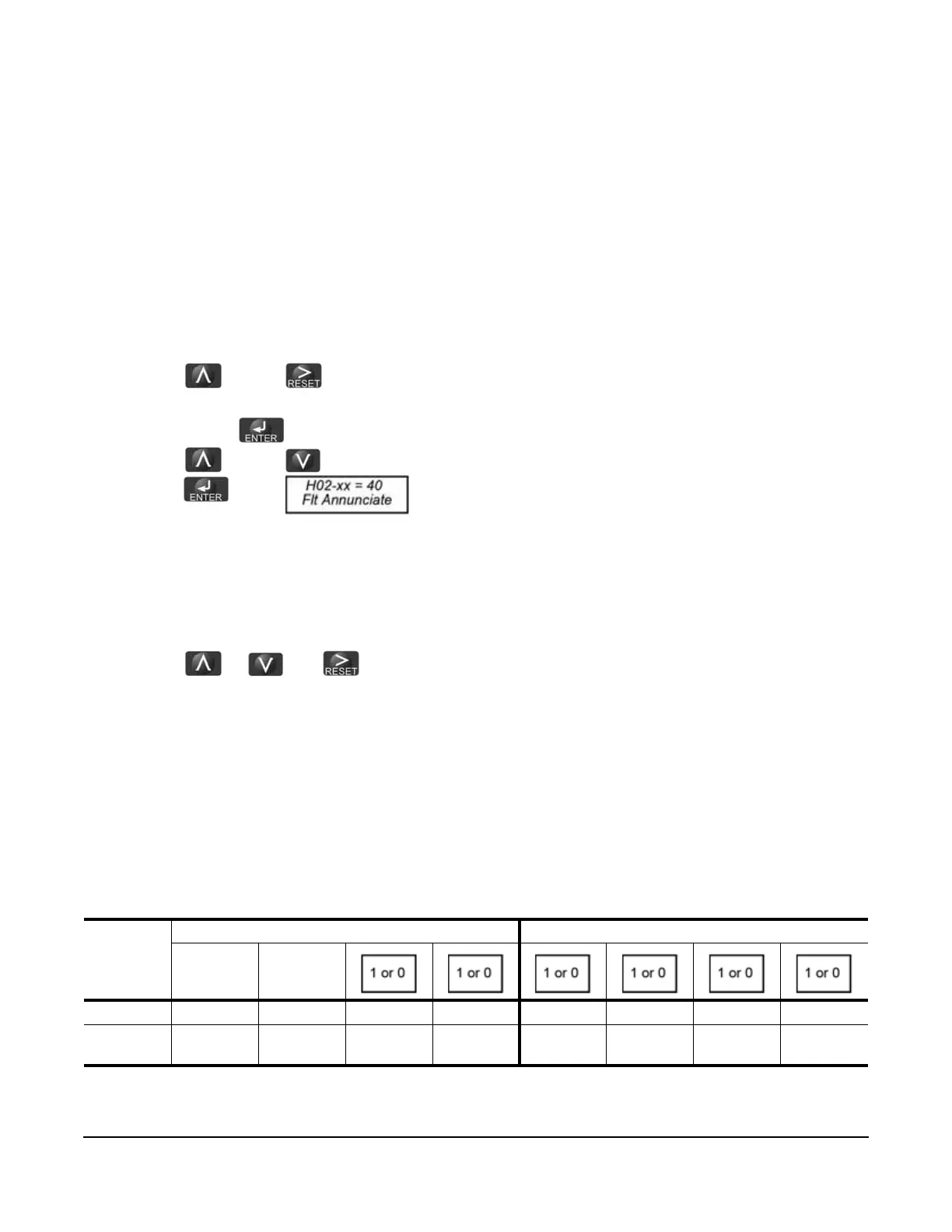
To program Digital Outputs—Fault Annunciate (from the Programming Menu):
1. Press the and the buttons to navigate to H02-01.
2. Determine the output terminal to which you want Fault Annunciate assigned; Terminals M0-M1, M2-M3 or
M5-M6 and press until the value blinks.
3. Press the and the button until H02-xx = 040 appears.
4. Press the button. appears.
5. From the worksheet in Table 5-76 on page 155, select one of three fault output sets (each row is a set). Enter
the one-zero combination that corresponds to the set (row) that you selected.
6. Determine which fault outputs should be enabled. To enable a fault output, enter 1 in the box above the fault
output; otherwise, enter 0. Do this for each fault output in the set.
7. Using the Binary to Hexadecimal Conversion chart (Table 5-78 on page 157), determine the 1-digit
hexadecimal number for both 4-digit binary numbers.
8. Press the or and buttons until the appropriate hexadecimal number appears and press
Enter.
Example: Select a fault annunciate set in which the fault you want to appear is shown. You must select only faults
from one set. If you want to have the relay output to change based on only inputs LL1 and UL1, you would choose
Set 2.
1. Place a “1” below LL1 and UL1 for Set 2.
2. Use table 5-78 to convert the left binary value “1 0 0 0” to Hex 8.
3. Use table 5-78 to convert the right binary value “1 0 1 0” to Hex A.
4. Enter this value into H02-xx.
Table 5-76: Fault Annunciate Example
First digit from the left = 8
Second digit from the left = A, so H02-xx = 8A
First digit from the left Second digit from the left
10
Set 2 1 0 OT1 OT2 LL1 LL2 UL1 UL2
Binary
Number
10001010

 Loading...


