IMPULSE
®
•G+ & VG+ Series 4 Technical Manual
November 2020
Page 157
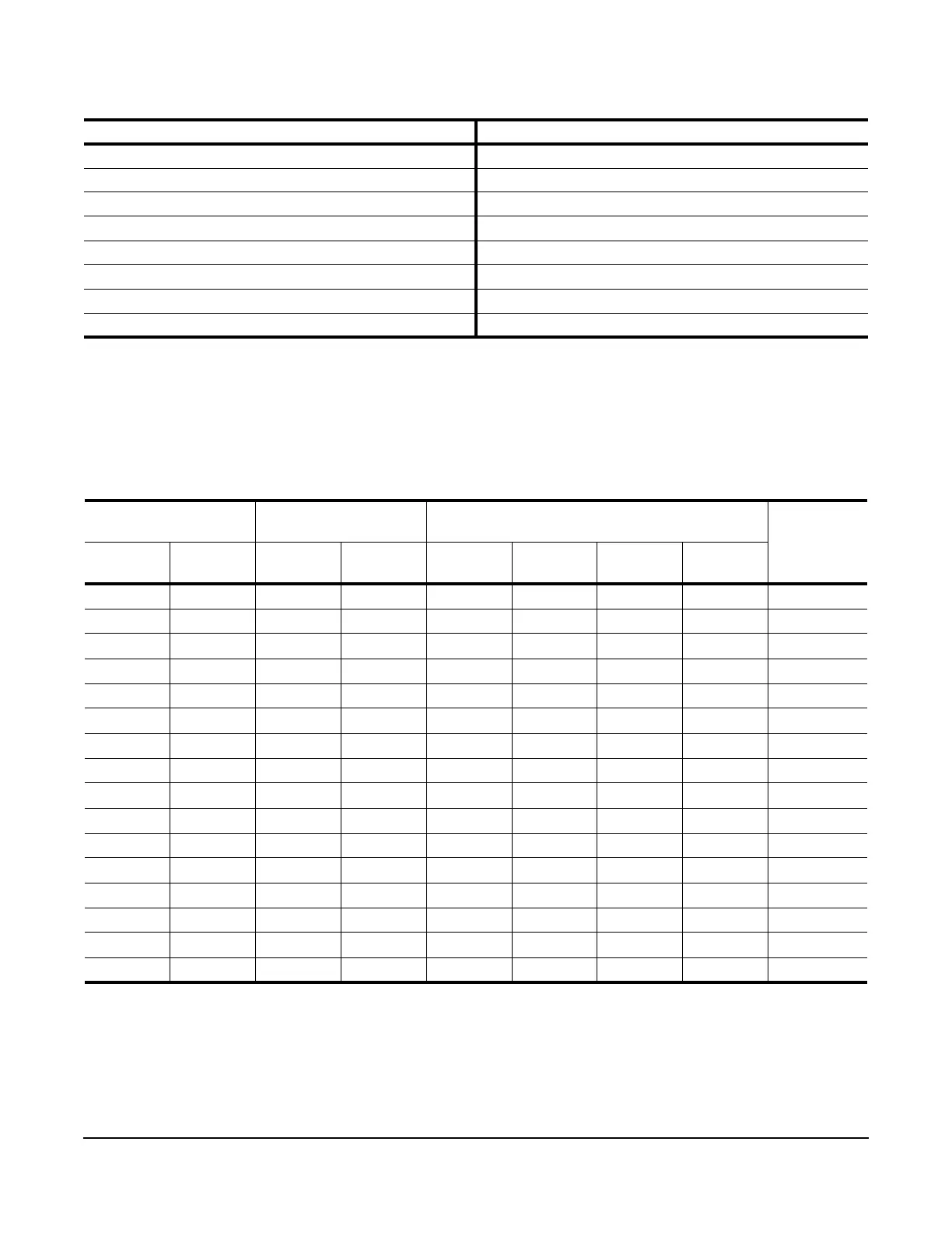
Table 5-78: Binary to Hexadecimal Conversion
5.6.5 External Fault Response Selection
It is sometimes desirable to have at least one external fault input to the VFD. To properly program a multi-function
input (H01-01 to H01-08) for this purpose an external fault response must be selected. The table below shows the
possible selections for an external fault response.
Table 5-79: External Fault Selection
(1) N.O. = normally open contact; N.C. = normally closed contact
(2) Uses B05-08 timer
Binary Number Hexadecimal Number Binary Number Hexadecimal Number
0000 0 1000 8
0001 1 1001 9
0010 2 1010 A
0011 3 1011 B
0100 4 1100 C
0101 5 1101 D
0110 6 1110 E
0111 7 1111 F
Input Level
Selection
Detection Method External Fault Action
MFDI Setting
Result
N.O.
(1)
N.C.
(1)
Always During Run Ramp to
Stop
Coast to
Stop
Fast Stop
(2)
Alarm Only
√√√ 20
√√ √ 24
√√ √ 28
√√ √2C
√√√ 22
√√√ 26
√√√2A
√√ √2E
√√ √ 21
√√ √ 25
√√ √ 29
√√ √2D
√√√ 23
√√√ 27
√√ √ 2B
√√ √2F

 Loading...


