IMPULSE
®
•G+ & VG+ Series 4 Technical Manual
November 2020
Page 47
* The 120 VAC, 42-48 VAC, and 24 VAC relays must be derated to 120 VAC for CE compliance.
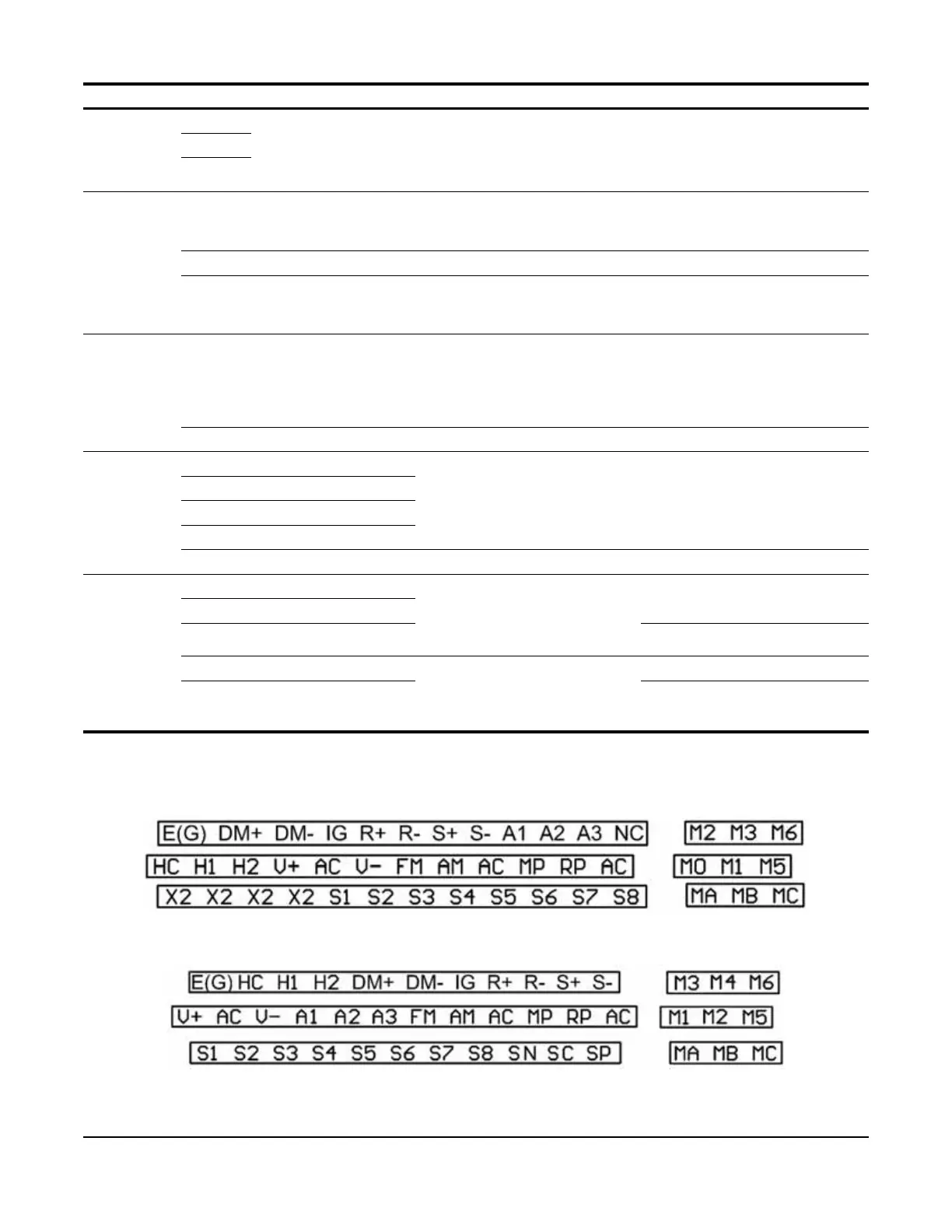
3.2.7.1 Interface Board (S4IF) Terminal Diagrams
Figure 3-14: S4IF Terminal Diagram (120 VAC, 42–48 VAC, 24 VAC)
Figure 3-15: S4IF Terminal Diagram (24 VDC)
Digital Output
Signals
(cont.)
MA Fault annunciate
Terminals MA-MC: N/O
Terminals MB-MC: N/C
Terminals MA & MC N/O; closed
at major faults
Terminals MB & MC N/C; open
at major faults
Form C Relay:
250 VAC*, 1 A; 30 VDC, 1 A
MB
MC
Analog
Outputs
FM MFAO 1 Multi-function analog output 1
(H04-01 to H04-03)
-10 to +10V, 2 mA
0 to +10V, 2 mA
4 to 20 mA
AC Analog Common Analog signal common 0 V
AM MFAO 2 Multi-function analog output 2
(H04-04 to H04-06)
-10 to +10V, 2 mA
0 to +10V, 2 mA
4 to 20 mA (24 VDC S4IF only)
Pulse I/O
Signal
RP Pulse Input Pulse input frequency reference
(H06-01)
Input Freq.: 0 to 32 kHz
Duty Cycle: 30 to 70%
High level: 3.5 to 13.2 VDC
Low Level: 0 to 0.8 VDC
Input Impedance: 3kΩ
MP Pulse Output Pulse output frequency (H06-06) 32 kHz (max)
RS-485/422 R+ Receive (+) For 2-wire RS-485, jumper R+ to
S+ and jumper R- to S-
RS-485/422 Line Driver
115.2 kbps (max)
R- Receive (-)
S+ Transmit (+)
S- Transmit (-)
IG Shield connection Serial Communication Shield 0 V (not grounded)
Safe Disable H1 Safe Disable input 1 • One or both open: Motor
Output Disabled
• Both closed: normal operation
• Off time of at least 1ms
24 VDC, 8 mA
Internal Impedance: 3.3kΩ
H2 Safe Disable input 2
HC Safe Disable common -
DM+ Safety monitor output Outputs the status of the Safe
Disable function. Closed when
both Safe Disable channels are
closed.
Up to 48 VDC, 50 mA
DM- Safety monitor output
common
-
Type Terminal Signal Function Description Signal Level

 Loading...


