IMPULSE
®
•G+ & VG+ Series 4 Technical Manual
November 2020
Page 89
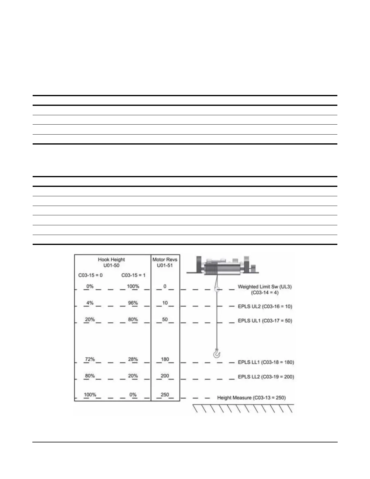
5.2.9 Electronic Programmable Limit Switches (EPLS)
Using the motor revolutions (U01-51) from the Height measurement function, it is possible to program UL1, UL2,
LL1, and LL2 positions without the use of rotary limit switches. When C03-16, C03-17, C03-18, or C03-19 has a
value other than 0, the EPLS function will be enabled. Height measurement must be correctly setup before using
EPLS.
Table 5-24: Electronic Programmable Limit Switches Parameter Settings
NOTE: A setting of 0 disables that specific limit.
Table 5-25: Limit Switch Outputs
Figure 5-10: EPLS Parameter Layout
Parameter Display Range Default
C03-16 UL2 Revolutions 0–65535 Rev 0
C03-17 UL1 Revolutions 0–65535 Rev 0
C03-18 LL1 Revolutions 0–65535 Rev 0
C03-19 LL2 Revolutions 0–65535 Rev 0
H02-0x or F05-0x = Function
2B - Upper Limit 1 Output ON when keypad displays UL1
2C - Upper Limit 2 Output ON when keypad displays UL2
2D - Lower Limit 1 Output ON when keypad displays LL1
2E - Lower Limit 2 Output ON when keypad displays LL2
30 - Lower Limit Output ON when keypad displays LL1 or LL2
31 - Up/Low Limit Output ON when keypad displays UL1, UL2, LL1, or LL2

 Loading...