IMPULSE
®
•G+ & VG+ Series 4 Technical Manual
November 2020
Page 46
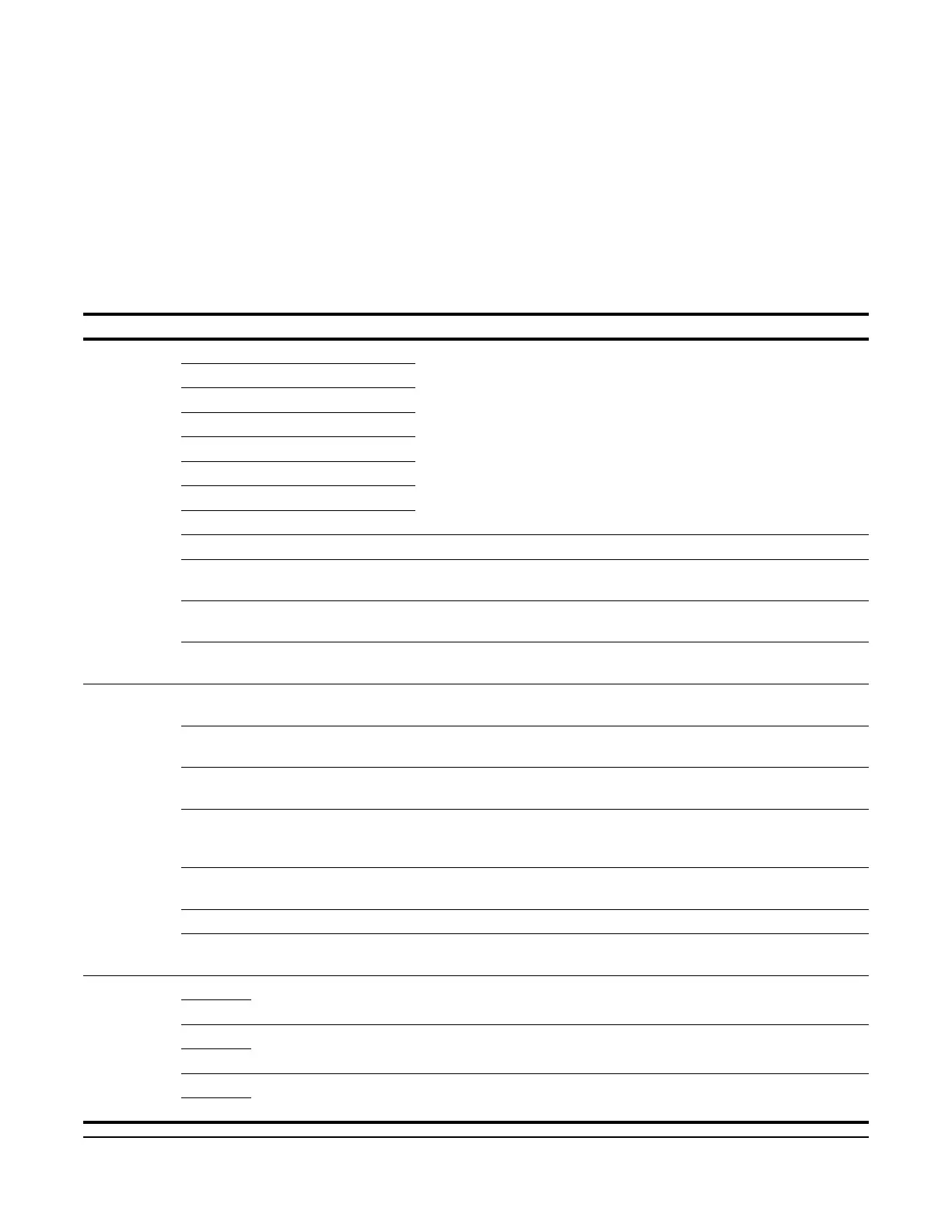
3.2.7 Control Circuit Terminals
The table below outlines the functions of the control circuit terminals.
Terms:
• Multi-Function Digital Input (MFDI)
• Multi-Function Digital Output (MFDO)
• Multi-Function Analog Input (MFAI)
• Multi-Function Analog Output (MFAO)
Table 3-8: Control Circuit Terminals
Type Terminal Signal Function Description Signal Level
Digital Inputs S1 MFDI 1 Multi-function digital inputs
(H01-01 to H01-08)
Photo-coupler isolation
120 VAC, 42-48 VAC, 24 VAC, or
24 VDC options; 8 mA per input
S2 MFDI 2
S3 MFDI 3
S4 MFDI 4
S5 MFDI 5
S6 MFDI 6
S7 MFDI 7
S8 MFDI 8
X2 MFDI Common Common for control signal 0 V
SC MFDI Common Only available on 24 VDC
interface board
0 V
SN MFDI Power Supply 0 V Only available on 24 VDC
interface board
0 V
SP MFDI Power Supply
+24 VDC
Only available on 24 VDC
interface board
24 VDC
Analog Inputs +V Power supply for analog
inputs
Positive supply for analog inputs +10.5 VDC, 20 mA
-V Power supply for analog
inputs
Negative supply for analog inputs -10.5 VDC, 20 mA
A1 MFAI 1 Multi-function analog input
(H03-02)
-10 to +10 V (impedance: 20kΩ)
0 to +10 V (impedance: 20kΩ)
A2 MFAI 2 Multi-function analog input
(H03-10)
10 to +10 V (impedance: 20kΩ)
0 to +10 V (impedance: 20kΩ)
4 to 20 mA (impedance: 250Ω)
A3 MFAI 3 Multi-function analog input
(H03-06)
-10 to +10 V (impedance: 20kΩ)
0 to +10 V (impedance: 20kΩ)
AC Analog Common Common for analog signal 0 V
E(G) Signal Common Ground for shielded lines and
option cards
-
Digital
Outputs
M0 MFDO 1 Multi-function digital output
(H02-01)
Form A Relay:
250 VAC*, 1 A; 30 VDC, 1 A
M1
M2 MFDO 2 Multi-function digital output
(H02-02)
Form A Relay:
250 VAC*, 1 A; 30 VDC, 1 A
M3
M5 MFDO 3 Multi-function digital output
(H02-03)
Form A Relay:
250 VAC*, 1 A; 30 VDC, 1 A
M6

 Loading...


