IMPULSE
®
•G+ & VG+ Series 4 Technical Manual
November 2020
Page 45
3.2.6.2 DIP Switch Functions
DIP Switches are described in this section. The functions of the DIP switches are shown in the table below.
Table 3-6: DIP Switches
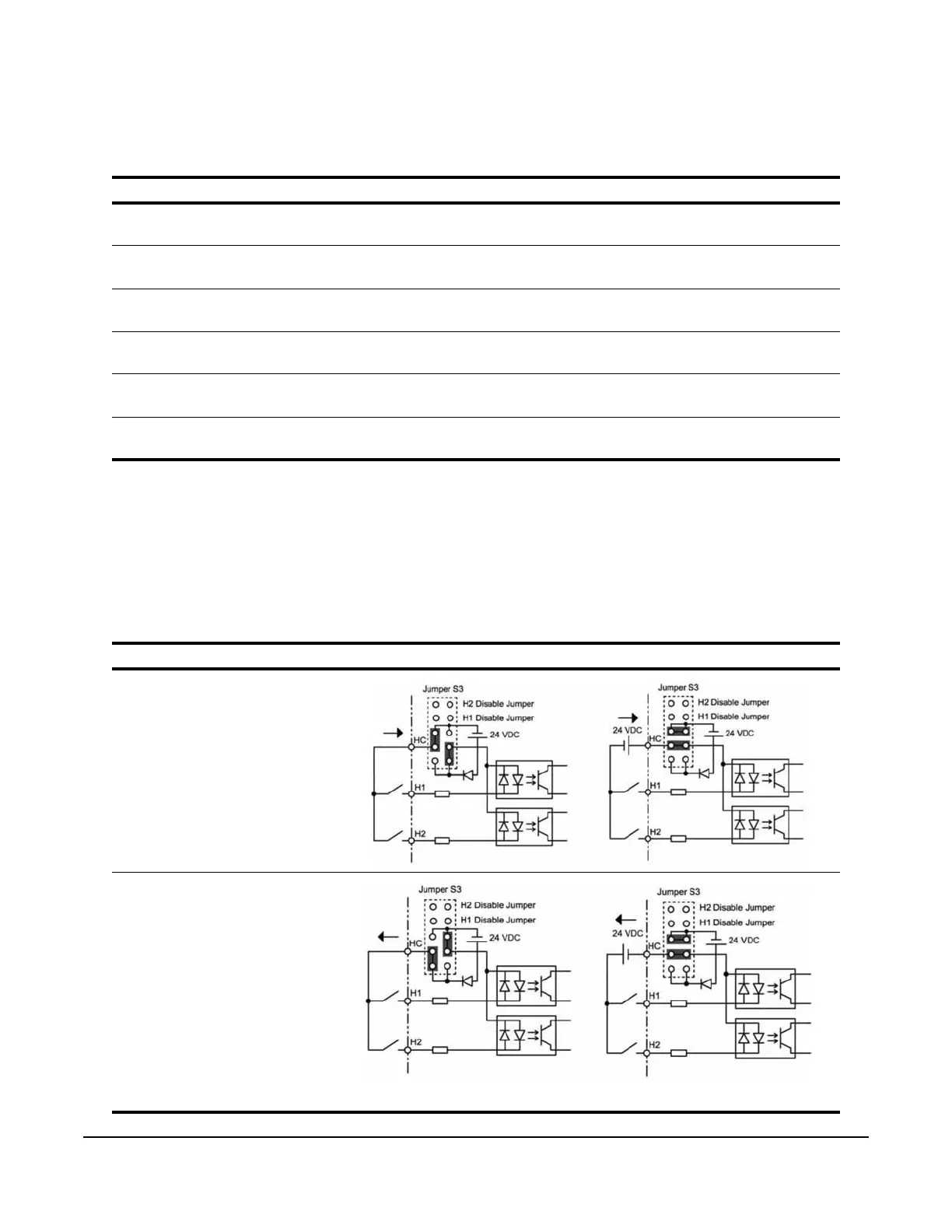
3.2.6.3 Sinking/Sourcing Mode for Safe Disable Inputs
Use jumper S3 on the Interface Board to select between Sink mode, Source mode, or external power for the Safe
Disable inputs H1 and H2 (as shown in Table 3-7). Jumper S3 is also used to disable the Safe Disable inputs H1
and H2, with the jumpers in place the Safe Disable inputs are disabled. Remove H1 and H2 disable jumpers if
external Safe Disable functionality is to be used. Refer to Figure 3-12 for locating jumper S3.
Table 3-7: Safe Disable Input Sink/Source/External Power Supply Selection
Name Function Setting
S1 Analog Input A2 Signal
Level
V: 0 to 10 VDC or -10 to 10 VDC (internal impedance: 20 kΩ) (default)
I: 4-20mA (internal impedance: 250 Ω)
S2 RS-485/RS-422
Termination Resistor
OFF: No terminating resistance (default)
ON: Terminating resistance of 120 Ω
S3 Hardware Base Block
Configuration
See page 3-19 for setting details
S4 Analog Input A3 Select AI: A3 is used as Analog Input 3 (default)
PTC: A3 is used with a Positive Temperature Coefficient (PTC) thermistor
S5 Analog Output FM
Signal Level
V: 0 to 10 VDC or -10 VDC to 10 VDC (default)
I: 4 to 20 mA
S6 DM+/DM- Polarity N.C.: Normally Closed (default)
N.O.: Normally Open
Mode VFD Internal Power Supply External 24 VDC Power Supply
Sinking Mode
Sourcing Mode
(Default)

 Loading...


