IMPULSE
®
•G+ & VG+ Series 4 Technical Manual
November 2020
Page 70
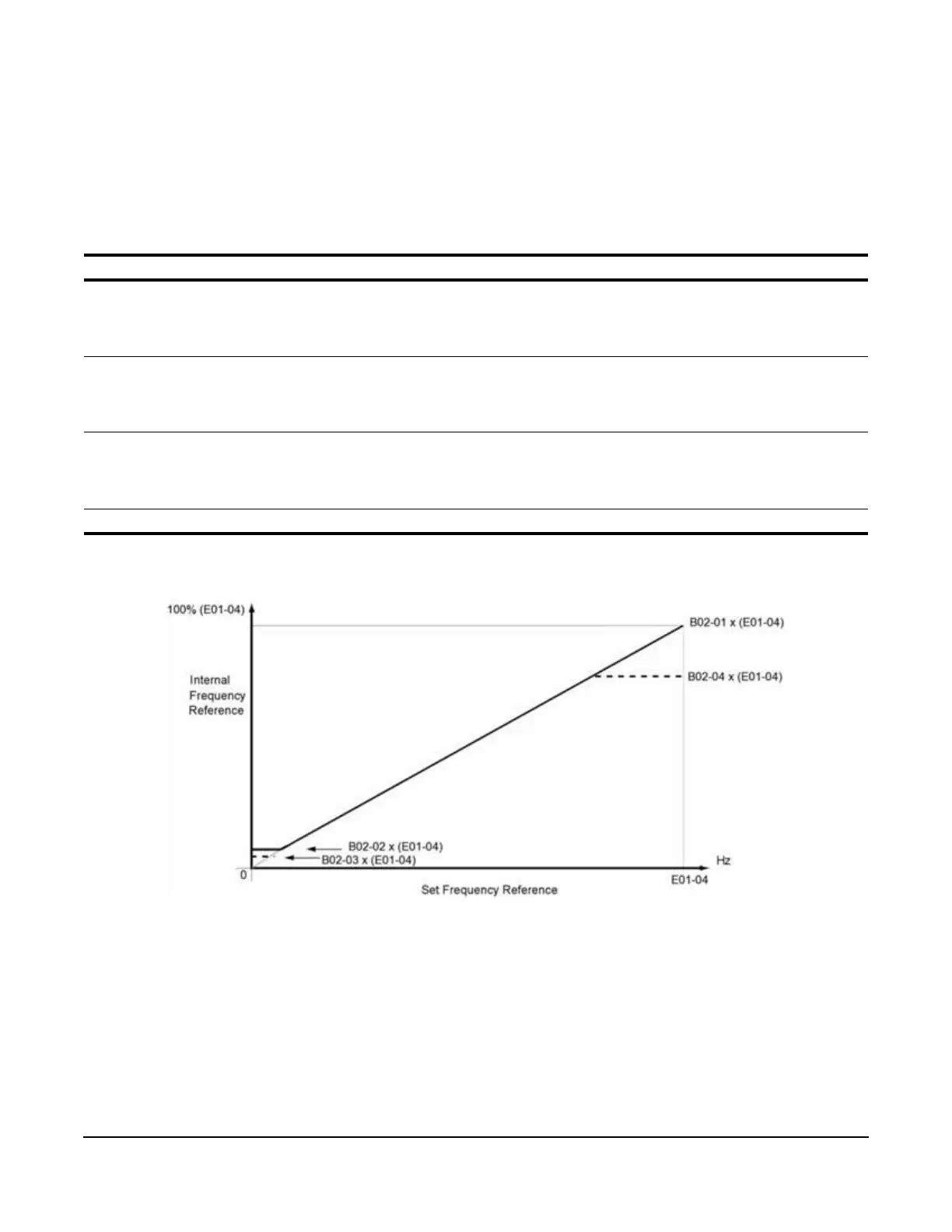
5.1.2 Reference Limits
These parameters limit the frequency range as a percentage of maximum output frequency (E01-04). If the lower
limit is below the DC Inj Start Freq (D01-01), then operation will continue according to B03-05.
An alternate upper limit frequency can be used during operation when a Multi-Function Digital Input (MFDI) is set to
59 (Alt F-Ref Up Lmt) and the MFDI is on.
Table 5-3: Reference Limit Parameter Settings
* Initial value is determined by X-Press Programming (Table 4-6 on page 59, Table 4-7 on page 60 or Table 4-8 on page 61).
Figure 5-1: Setting Frequency Upper and Lower Limits
Parameter Display Function Range Default
B02-01 Ref Upper Limit Sets as a percentage of the maximum
output frequency (E01-04), which
determines the maximum frequency at
which the VFD is able to run.
0.0–110.0% 100.0*
B02-02 Ref Lower Limit Sets as a percentage of the maximum
output frequency (E01-04), which
determines the minimum master frequency
reference only.
0.0–110.0% 0.0
B02-03 Ref1
Lower Limit
Sets as a percentage of the maximum
output frequency (E01-04), which
determines the minimum frequency at
which the VFD is able to run.
0.0–110.0% 2.0*
B02-04 Alt Upper Limit Alternate of B02-01 set by MFDI=59. 0.0–110.0% 0.0

 Loading...


