IMPULSE
®
•G+ & VG+ Series 4 Technical Manual
November 2020
Page 118
5.3 Tuning
• D01 DC Injection Braking
• D02 Motor Slip Compensation
• D03 Torque Compensation
• D04 Automatic Speed Regulator (ASR) Tuning
• D05 Torque Control
• D08 Dwell
• D09 S-Curve Acceleration/Deceleration
• D10 Carrier Frequency
• D11 Hunting Prevention
5.3.1 DC Injection
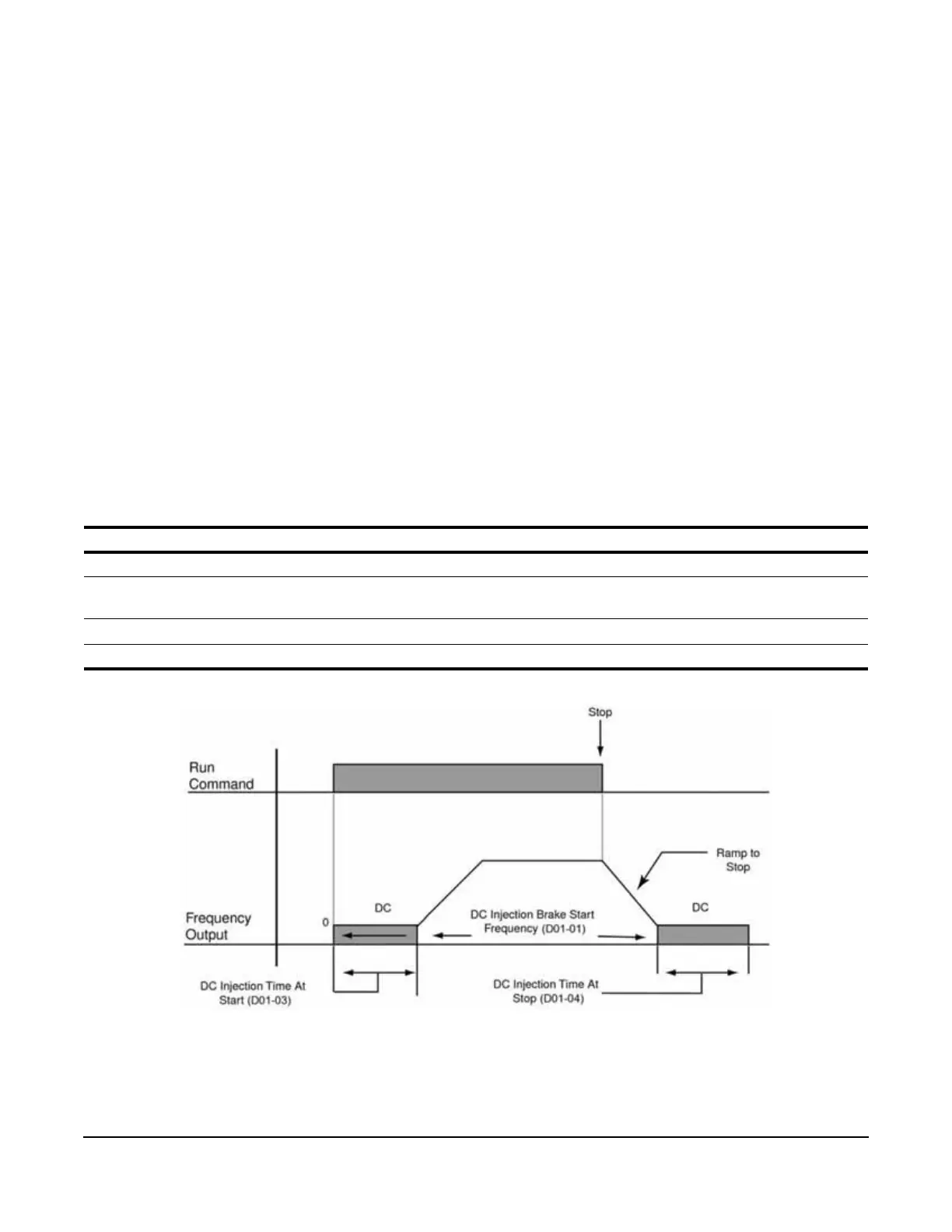
With decel to stop enabled (B03-03=0), upon removal of the run command, the IMPULSE
®
•G+ and VG+ Series 4
VFD controls motor deceleration according to the Decel Time setting (B05-02), until output frequency reaches the
DC Injection Braking Start Frequency (D01-01 setting). Then the IMPULSE
®
•G+ and VG+ Series 4 frequency
output is turned off and DC injection current is applied to the motor. The effective DC injection time and current
should be set to provide adequate stopping without excessive motor heating. The DC injection voltage is
determined by the DC injection braking current and motor impedance.
Table 5-44: DC Injection Parameter Settings
* Not available in the Flux Vector control method (A01-02 = 3).
Figure 5-17: DC Braking Sequence
Parameter Display Function Range Default
D01-01 DCInj Start Freq DC Injection Braking Frequency Start 0.0–10.0 Hz 0.5
D01-02* DCInj Current Sets the DC Injection Braking current as a
percentage of the VFD rated current.
0–100% 50
D01-03 DCInj Time@Start DC Injection Braking Time 0.00–10.00 sec 0.00
D01-04 DCInj Time@Stop DC Injection Braking Time at Stop 0.00–10.00 sec 0.05
 Loading...