IMPULSE
®
•G+ & VG+ Series 4 Technical Manual
November 2020
Page 129
5.4 Motor Parameters
• E01 V/f Pattern
• E02 Motor Setup
• E03 Test Mode Configuration
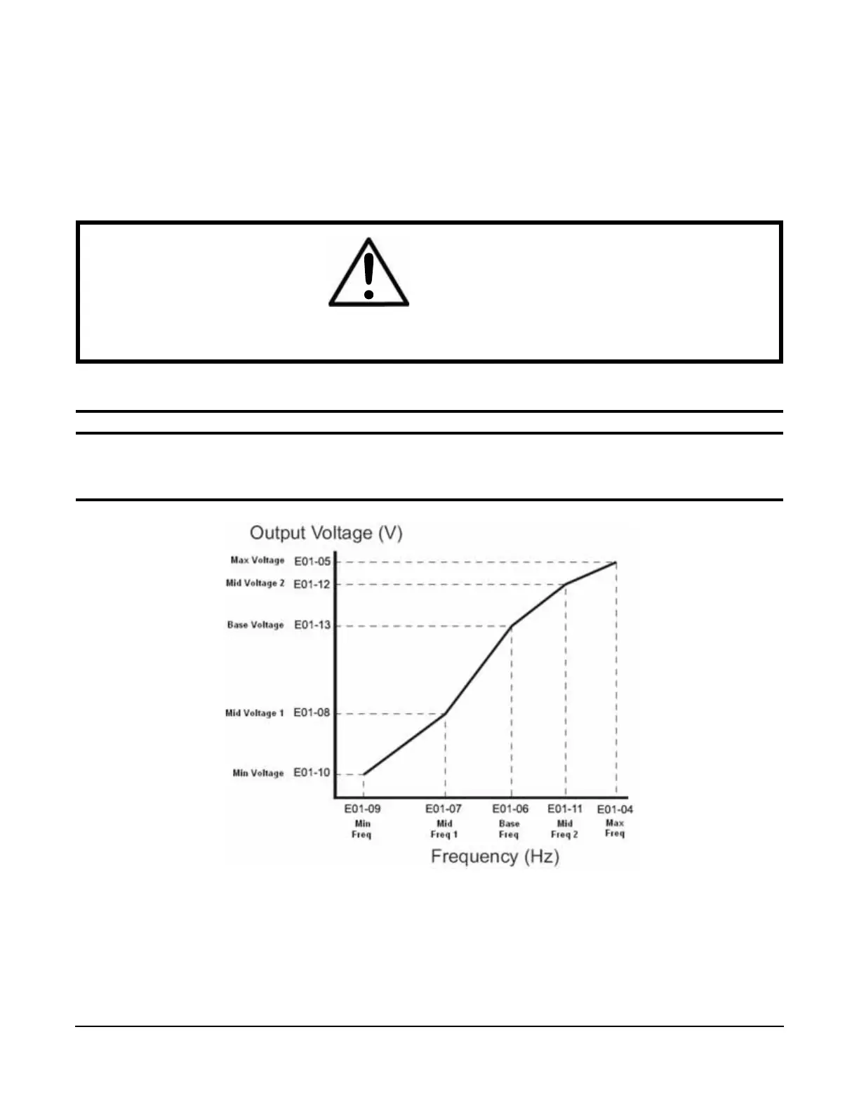
5.4.1 Voltage/Frequency Pattern
Table 5-54: V/f Pattern Parameter
Figure 5-24: Output Voltage
• Factory setting is 230 (230V units) or 460 (460V units).
• When E01-11 = 0, then the value of E01-11 is not used.
• When E01-12 = 0, then the value of E01-12 is not used.
• When E01-13 = 0, then the value of E01-13 is not used.
Parameter Display Function Range Default
E01-01 Input Voltage Sets input voltage 230V: 155–255 VAC
460V: 310–510 VAC
575V: 446–733 VAC
230
460
575
WARNING
VFD input voltage (not motor voltage) must be set in E01-01 for the protective features of the VFD to function
properly. Failure to do so may result in equipment damage and/or death or personal injury.

 Loading...


