IMPULSE
®
•G+ & VG+ Series 4 Technical Manual
November 2020
Page 50
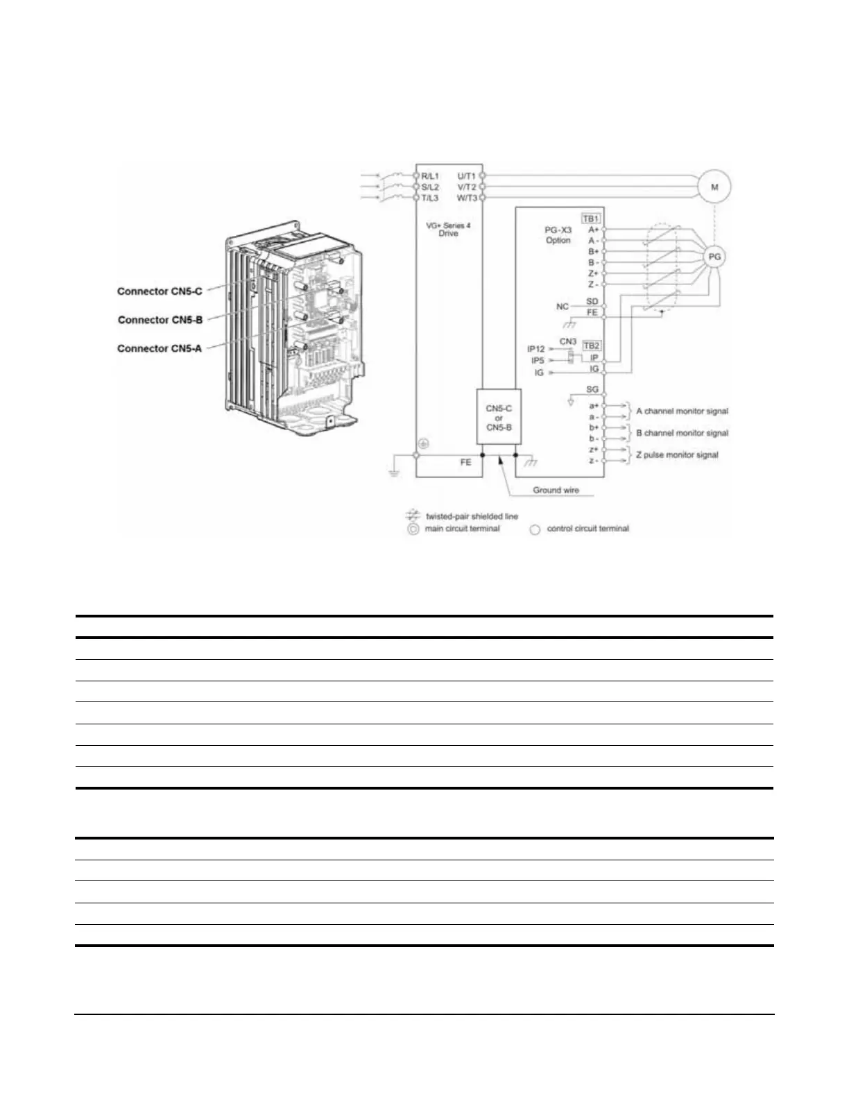
3.3.2 Encoder Wiring Diagrams and Information
Encoder 1: Install in option port CN5-C
Encoder 2: Install in option port CN5-B
Figure 3-17: PG-X3 Encoder Card Wiring
Table 3-10: Encoder Wiring
Table 3-11: PG-X3 Option Card Specifications
NOTE: See PG-X3 installation manual for wiring and terminal descriptions.
Encoder Signal Wire Color PG-X3 Terminal
+5 or 12 VDC (select via CN3 jumper) Red IP
0V Black IG
A+ Blue A+
A- Gray A-
B+ Green B+
B- Yellow B-
Shield - FE
Power supply to encoder: +5 VDC or +12 VDC; 200 mA maximum
Encoder input signal: RS-422–level, line-driver-type
Pulse monitor output signal (repeater): RS-422–level, line-driver-type or open collector
Pulse phases accepted: Differential phases A and B (both + and -)
Maximum input frequency: 300 kHz

 Loading...


