IMPULSE
®
•G+ & VG+ Series 4 Technical Manual
November 2020
Page 124
5.3.5.1 Speed/Torque Control Switching
Speed control or torque control is used in traverse applications and can be selected “on the fly” with the VG+ VFD
by using the digital input speed/torque control selection (H01-xx = 34).
Table 5-49: Speed/Torque Control Switch Parameters
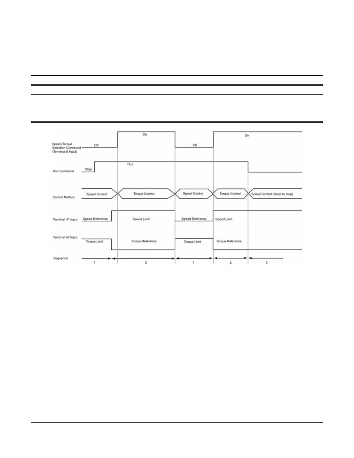
Figure 5-21: Speed/Torque Control Selection Timing Diagram
1. When the speed/torque control selection is OFF, speed control is activated.
• Speed reference during speed control depends on the frequency reference selection (B03-01) setting. To
use terminal A1, A2, or A3 as the master frequency reference, set B03-01 = 1.
• Torque limit during speed control is the smaller of the absolute value of terminal A2 or A3 torque limit, or
the values set in the torque limit parameters (C07-01 to C07-04) is used as the torque limit.
• When a stop command is given during speed control, speed control is maintained as the motor
decelerates to stop and the smaller of the absolute value of the terminal A2 or A3 torque limit, or the values
set in the torque limit parameters (C07-01 to C07-04) is used as the torque limit.
2. When the speed/torque control selection is ON, torque control is activated.
• Speed limit during torque control is the master frequency reference at terminal A1, A2, or A3 when speed
limit selection (D05-03) is set to “1”, and is the speed limit value (D05-04) when D05-03 = “2”, regardless of
the frequency reference selection (B03-01) setting.
• During torque control, the terminal A2 or A3 analog input value becomes the torque reference.
3. By giving a stop command during torque control, operation changes to speed control automatically, and the
motor decelerates to stop. The torque limit during deceleration to stop becomes the values set in the torque
limit parameters (C07-01 to C07-04).
Terminal Parameter Setting Description
S1 - S8 H01-01–H01-08 34 Speed/torque control selection
A1 B03-01
D05-03
1
1
Frequency reference selection (terminals A1, A2, or A3)
Speed limit selection (terminals A1, A2, or A3)
A3/A2 H03-06/H03-10 13 Torque reference/torque limit

 Loading...


