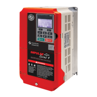
IMPULSE
®
•G+ & VG+ Series 4 Technical Manual
November 2020
Page 20
2.2 System Components
2.2.1 Standard Components
• Interface Board (120 VAC, 42-48 VAC, 24 VAC, or 24 VDC)
• PG-X3 Line Driver Encoder Option Card (VG+ only)
2.2.2 Optional VFD Components
• DI-A3 Digital DC Input Card
• DO-A3 Digital Output Card
• AI-A3 Analog Input Card
• AO-A3 Analog Output Card
• S4I Digital AC Input Card
• S4IO Digital AC Input/Output Card
• PS-A10L 24 VDC Control Power Unit for 230 V models
• PS-A10H 24 VDC Control Power Unit for 460 V and 575 V models
• PG-B3 Open Collector Encoder Card
• SI-EN3 EtherNet/IP
• SI-EN3D EtherNet/IP (Dual-Port)
• SI-EM3 Modbus TCP/IP
• SI-EM3D Modbus TCP/IP (Dual-Port)
• SI-EP3 PROFINET
• SI-P3 PROFIBUS-DP
2.2.3 As-Required VFD Components
• AC reactor - line or load
• DC bus choke
• External dynamic braking resistor(s)
• External dynamic braking unit
2.2.4 Required Control Components
•Motor
• User input device (pendant, joystick, PC, PLC, radio, or infrared control)
• External circuit protection devices (fuses or circuit breakers). See Section 3.2 on page 33.
• R-C surge suppressors on contactor coils

 Loading...