EasyManuals Logo

Magnetek IMPULSE G+ 4 Series User Manual

Magnetek IMPULSE G+ 4 Series
256 pages
To Next Page IconTo Next Page
To Previous Page IconTo Previous Page
Page #23 background imageLoading...
Page #23 background image
IMPULSE
®
•G+ & VG+ Series 4 Technical Manual
November 2020
Page 23
2.4 Installation Orientation
Figure 2-2: Standard Installation Orientation
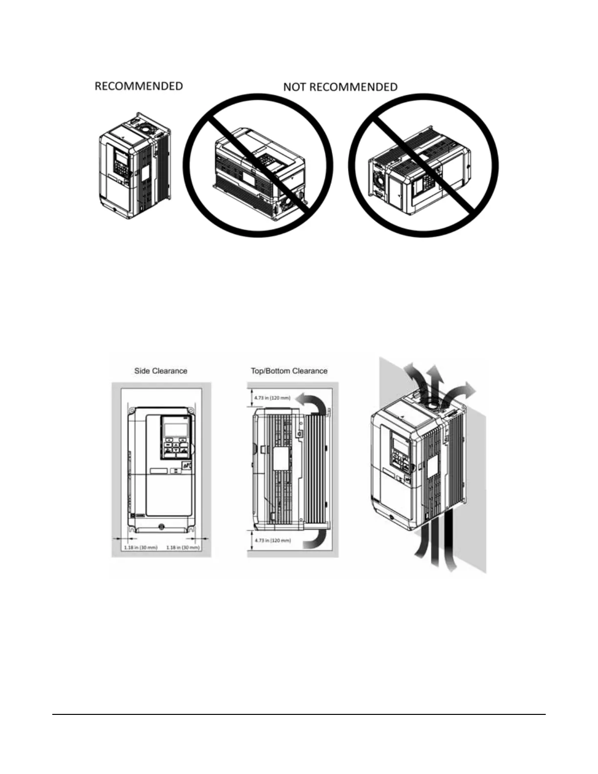
2.5 Installing the VFD (Recommended Clearances)
The following two figures show the recommended minimum clearances when mounting the VFD in standard or
side-by-side installations. If the recommended clearances can't be met, decreased airflow may reduce the life of
the VFD.
Figure 2-3: Standard Installation
A – 1.97 in (50 mm) minimum C – 1.18 in (30 mm) minimum
B – 4.73 in (120 mm) minimum D – Airflow direction

Table of Contents

Other manuals for Magnetek IMPULSE G+ 4 Series

Questions and Answers:

Question and Answer IconNeed help?

Do you have a question about the Magnetek IMPULSE G+ 4 Series and is the answer not in the manual?

Magnetek IMPULSE G+ 4 Series Specifications

General IconGeneral
BrandMagnetek
ModelIMPULSE G+ 4 Series
CategoryDC Drives
LanguageEnglish

Related product manuals