IMPULSE
®
•G+ & VG+ Series 4 Technical Manual
November 2020
Page 225
6.7 S4IF Replacement Procedure
NOTE: When handling boards always use electrostatic discharge protection. Keep the boards in the ESD bag as
long as you can. Do not lay the board on any surfaces without ESD protection. When handling, always hold
the board from the edges and do not touch the components. Installation should be performed only by
qualified personnel who are familiar with this type of equipment and the hazards involved.
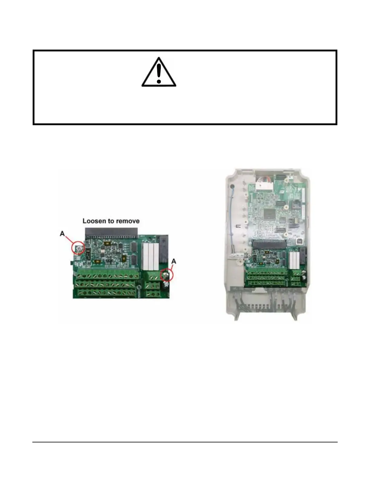
Figure 6-2: Location of Retaining Screws
1. Prior to installation, record all modified parameters.
2. Set A01-05 = 7770 (this prepares all modified and user parameters for IF card removal).
3. Disconnect all electrical power to the VFD.
4. Remove the VFD's front cover.
5. Verify that the “CHARGE” indicator lamp inside the VFD is OFF (may take up to 5 minutes).
6. Use a voltmeter to verify the voltage at the incoming power terminals (L1, L2, and L3) has been disconnected.
7. Follow your local ESD procedures.
8. Loosen the two retaining screws (A) pictured in Figure 6-2.
9. Remove existing interface card by grasping each corner at TB6 and TB5 and slide down until free.
10. Return I/O board to ESD bag.
WARNING
Do NOT touch any circuit components while AC main power is on or immediately after the main AC power is
disconnected from the unit. You must wait until the red “CHARGE” lamp is extinguished. It may take as long as
10 minutes for the charge on the main DC bus capacitors to drop to a safe level. Failure to adhere to this
warning could result in serious injury.

 Loading...


