Grove Published 3-22-2021, Control # 702-02 4-139
GRT8120 OPERATOR MANUAL OPERATING PROCEDURES
Extending and Locking the Telescoping Cylinder
Under no circumstances should you select and press the
lock symbol (1, Figure 4-132) while the tele cylinder is in
motion.
Slowly move the telescoping cylinder into the next extended
telescopic section.
At the locking point:
• The display (2, Figure 4-128) shows the length for the
current locking point, refer to Table 4-3
• The proximity switch indicators for S2117N, S2118N,
and S2116N are used to align the tele cylinder to the
hole in the boom section. S2118N is on whenever the
tele cylinder pins are in the “foot section” or the near end
of the boom section weldment where the hole is located.
S2116N goes on when the tele cylinder has extended
beyond the hole. S2117N goes on when the tele cylinder
is not extended enough to reach the hole. Therefore,
one would operate the tele cylinder until S2118N is on,
and S2116N and S2117N are off. This is what is shown
in Figure 4-133.
• Select and confirm the symbol shown as Item 4 in
Figure 4-129.
The telescoping cylinder is locked, if the actuator is able to
release the cylinder pins, and the tele cylinder is actually
aligned with a pinning location hole in the boom section. The
screen should appear as shown in Figure 4-132.
• You can now operate this telescopic section, refer to
Retracting and Locking a Telescopic Section, page
4-137.
Tables for Approaching the Locking Points
The extent to which the telescoping cylinder has to be
extended in order to reach a locking point depends on
whether you want to lock:
• the telescoping cylinder or
• a telescopic section.
Locking Points for the Telescoping Cylinder
Table 4-3 shows the extended length for locking the
telescoping cylinder.
Locking Points for the Telescopic Sections
Table 4-1 shows the extended length for locking the
telescopic boom sections. The telescopic section should not
be set down for locking or unlocking it.
The cutout (1, Figure 4-134 must be clear. That is why you
have to extend the telescoping cylinder further than with a
return run.
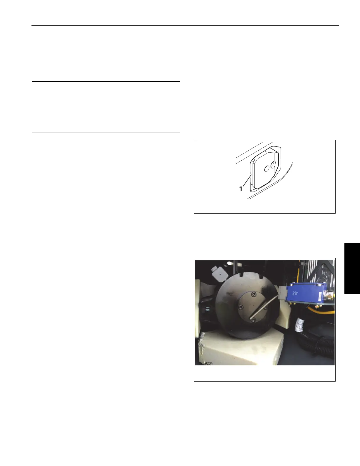
Telescoping Cylinder Boom Nose Switch
A whisker-style trigger switch is installed at the boom nose to
detect the tele cylinder barrel being too close to the boom
nose. This switch is shown as triggered in Figure 4-135.
CAUTION
Machine Damage Hazard!
If you select Lock while the telescoping cylinder is
moving, the locking pins on the telescopic section are slid
out immediately and they can damage or tear the
electrical or hydraulic components in the main boom.

 Loading...


