OPERATING PROCEDURES GRT8120 OPERATOR MANUAL
4-140 Published 3-22-2021, Control # 702-02
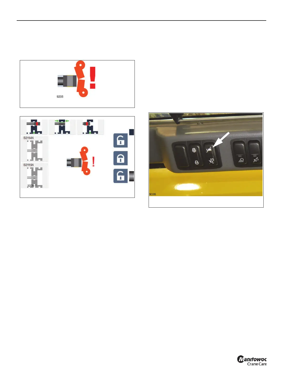
When this switch is triggered, the symbol shown in
Figure 4-136 should appear on the left side of the ODM
display or in the middle of the Emergency Mode screen
Figure 4-137.
In this triggered condition, the telescoping cylinder is no
longer expected to be able to extend. If the telescoping
emergency program is being used, then it is still possible to
still extend the cylinder (such as when the switch is
malfunctioning or disconnected), but this should only be
done with physical verification of the location of the
telescoping cylinder with respect to the boom nose. If the
telescoping cylinder impacts the boom nose, the boom
system will be damaged.
With the telescoping cylinder not moving, and with the
controller not being used, then the bypass switch
(Figure 4-138) can be used. The telescoping cylinder will
now extend, but when the telescoping cylinder stops moving,
or if the controller is no longer used, then the same steps
must be repeated to use the bypass switch.

 Loading...


