5-46 Published 3-22-2021, Control # 702-02
SET-UP AND INSTALLATION GRT8120 OPERATOR MANUAL
NOTE: This procedure assumes the boom extension and
fly section are installed on the side of the main
boom.
1. Make sure the counterweight is installed. For more
information about installing the counterweight, see
Counterweight Removal and Installation, page 5-66.
1. Make sure the crane is set up on fully extended
outriggers. For more information, see Using the
Outriggers, page 4-19.
2. Fully retract and lower the boom to horizontal.
3. Connect boom extension electrical connectors. For
more information, see Boom Extension Electrical
Connections, page 5-51.
4. If erecting a hydraulic boom extension, connect
hydraulic hoses. For more information, see Hydraulic
Boom Extension Connections, page 5-52.
5. If erecting an optional hydraulic boom extension, make
sure the angle indicator (1, Figure 5-66) is aligned. If the
arrows are not aligned, adjust the boom extension offset
as needed to align the arrows. For more information, see
Offsetting the (Optional) Hydraulic Boom Extension,
page 5-57.
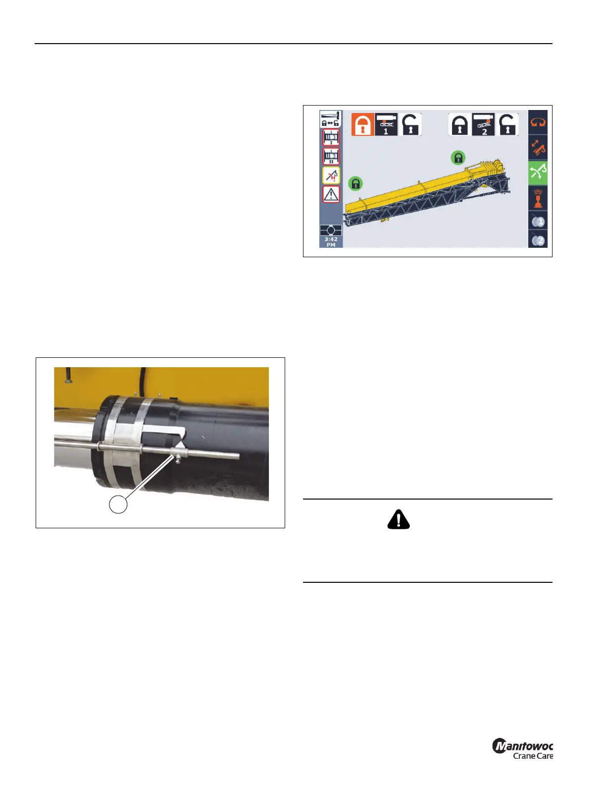
6. In the ODM, verify that the front (Pin #2) and rear (Pin
#1) boom extension pins are securely installed. Visually
confirm that the pins are installed.
7. Attach a tag line to the tip of the boom extension base
section near the sheave. The tag line will assist when
swinging the boom extension to the boom nose.
8. Detach the fly section from the boom extension base
section by removing the retaining clip (2, Figure 5-61)
and pin (3) securing the connecting link (1) to the boom
extension fly section (4).
9. Retract the retaining pin (1, Figure 5-45) from the
bracket (2) to release the rear boom extension ramp (3)
from the stowed position. Fully swing the rear boom
extension ramp (3) into the erected position. Make sure
the pin (4) locks into position on the rear boom extension
bracket (5).
10. Visually confirm the rear boom extension pin (Pin #1 in
the ODM) (2, Figure 5-27) properly secures the fly
section to the main boom. Visually confirm the pin at the
middle fly section mounting bracket (9, Figure 5-27)
properly secures the fly section to the main boom.
CAUTION
After removing the retaining clip and pin that secures the
boom extension base section to the fly section, the boom
extension is free to swing away from the side of the main
boom.

 Loading...


