64Z8046A
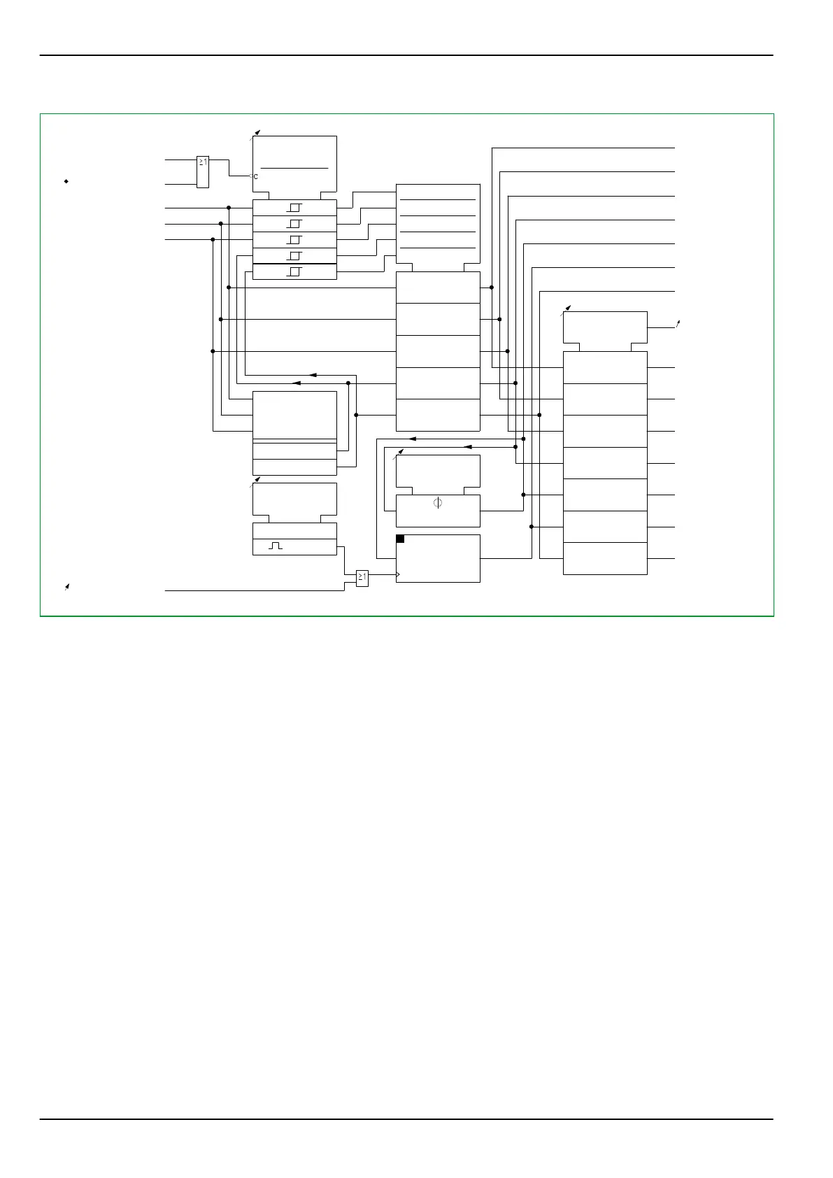
MAIN:
General starting
[ 036 000 ]
MAIN:
Current IA,a p.u.
MAIN:
Current IB,a p.u.
MAIN:
Current IC,a p.u.
MAIN:
Curr. IP,max,a p.u.
MAIN:
IP,max p.u.,stored a
MAIN:
IP,max p.u.,delay a
MAIN:
Curr. IP,min,a p.u.
MAIN:
Inom C.T.prim.,end a
MAIN:
Inom C.T.prim.,end a
MAIN:
Current IA,a prim.
MAIN:
Current IB,a prim.
MAIN:
Current IC,a prim.
MAIN:
Curr. IP,max,a prim.
MAIN:
IP,max prim.,delay a
MAIN:
IP,max prim.stored a
MAIN:
Curr. IP,min,a prim.
MAIN:
Meas. value rel. IP
[ 011 030 ]
MAIN:
Settl. t. IP,max,del
[ 010 113 ]
MAIN:
Reset IP,max,st.USER
[ 003 033 ]
0
1
0: don't execute
1: execute
MAIN:
General reset USER
[ 003 002 ]
1: execute
MAIN:
Hardware fault
306 018
IA,z
IB,z
IC,z
Imax,z
Imin,z
COMP
c1
c2
c3
c4
c5
1
2
3
4
5
R
Fig. 3-46: Measured operating data for the phase currents, shown here for end a
3.12.6.2.2 Measured Operating Data for the Residual Currents
The following diagram shows the measured operating data for the residual
currents of the transformer ends a, b and c, Fig. 3-48, (p. 3-79) shows the same
information for end d.
The parameters given in Fig. 3-47, (p. 3-79) apply to transformer end a. The
corresponding parameters of the transformer ends b and c are given in
Chapter 7, (p. 7-1) and Chapter 8, (p. 8-1).
P634 3 Operation
3-78 P634/EN M/R-42-A // P634‑311‑653