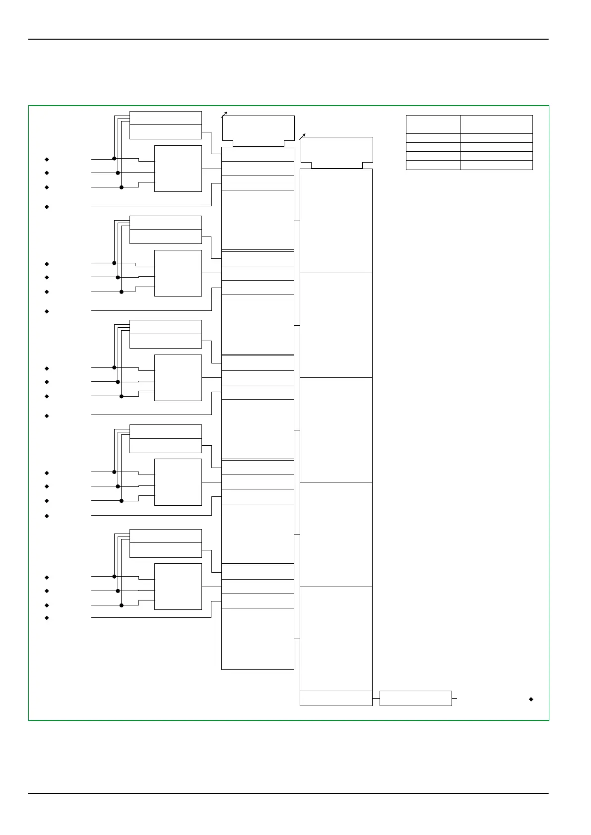
3.25.3 Selection of Current
64Z8945A
1
0
THRM1:
Select current PSx
[ * ]
0: Max. phase current
1: IN calculated
∑
IA,a
2
2: IN measured
IB,a
IC,a
IN,a
+
+
+
COMP
Imax
0 . . . 2
THRM1:
I
0
THRM1:
Select. meas. input
[ 019 109 ]
AR_MV
1
0
∑
IA,b
2
IB,b
IC,b
IN,b
+
+
+
COMP
Imax
0 . . . 2 1
1
0
∑
IA,c
2
IB,c
IC,c
IN,c
+
+
+
COMP
Imax
0 . . . 2 2
1
0
∑
IA,d
2
IB,d
IC,d
+
+
+
COMP
Imax
0 . . . 2 4
1
0
∑
ΣIA
2
ΣIB
ΣIC
+
+
+
COMP
Imax
0 . . . 2 3
0 . . . 4
Parameter
set 1
set 2
set 3
set 4
THRM1:
Select current PSx
013 184
013 185
013 186
013 187
ΣIN
IN,d
Fig. 3-129: Selection of measured values for thermal overload protection.
The measured values to be monitored by the respective thermal overload
protection functions are selected using several independent setting parameters:
THRM1: Select. meas. input selects either a particular transformer end or
P634
3 Operation
3-176 P634/EN M/R-42-A // P634‑311‑653