3.26 Time-Voltage Protection (Function Group V<>)
The two-stage time-voltage protection function provided by the P634 evaluates
the fundamental wave of the phase voltages.
3.26.1 Disabling and Enabling V<> Protection
V<> protection can be disabled or enabled using setting parameters. Moreover,
enabling can be carried out separately for each parameter subset.
3.26.2 V<> Protection Readiness
V<> protection is ready if it is enabled and no fault has been detected in the
voltage-measuring circuit by the measuring-circuit monitoring function.
S9Z5006A
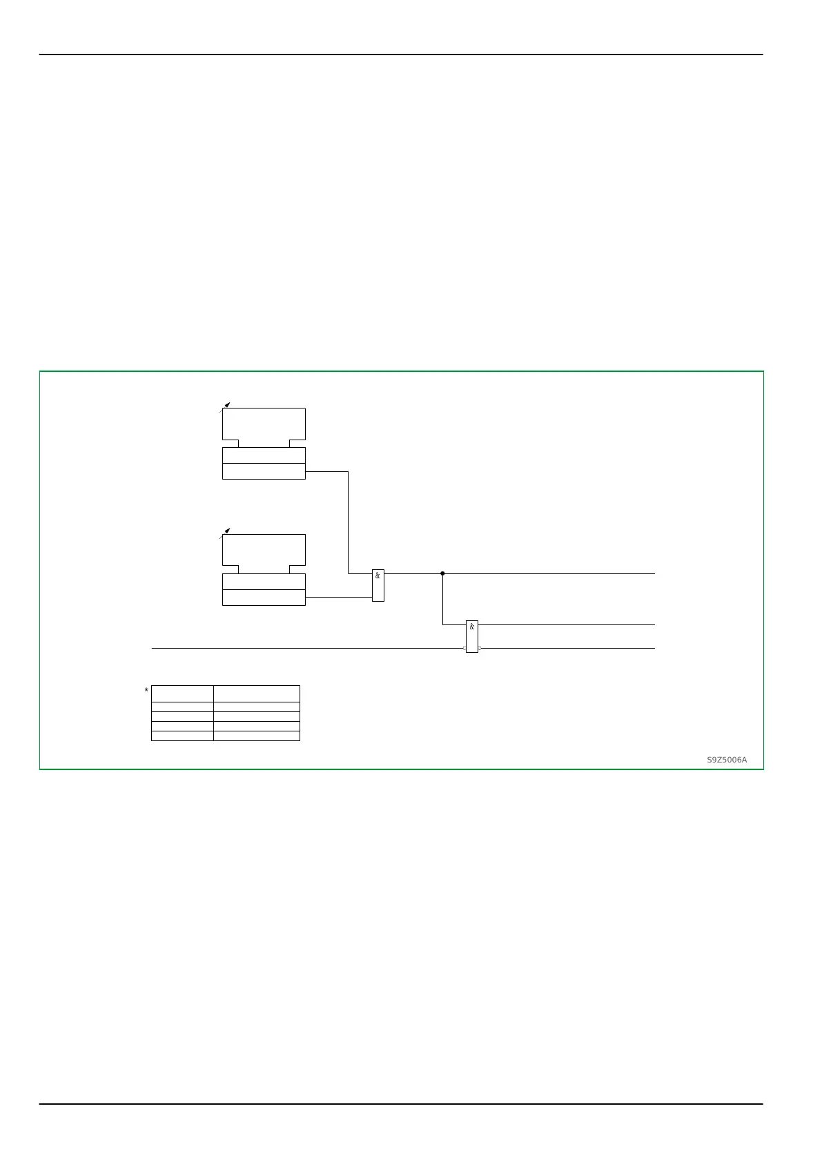
V<>:
Enabled
[ 040 066 ]
V<>:
Enable PSx
076 000
077 000
078 000
079 000
Parameter
set 1
set 2
set 3
set 4
1
0
V<>:
Enable PSx
[ * ]
0: No
V<>:
General enable USER
[ 023 030 ]
1
0
0: No
1: Yes
V<>:
Ready
[ 042 003 ]
V<>:
Not ready
[ 042 004 ]
1: Yes
MAIN:
M.c.b. trip V EXT
[ 004 061 ]
Fig. 3-134: Enabling, disabling and readiness of V<> protection.
3.26.3 Voltage Monitoring
The P634 checks the voltage to determine whether it exceeds or falls below a set
threshold. The triggers are followed by timer stages that can be blocked via
appropriately configured binary signal inputs.
If undervoltage monitoring decisions are to be included in the trip commands,
then it is recommended that transient signals be used. Otherwise the trip
command would always be present when the system voltage was disconnected,
and it would therefore not be possible to close the circuit breaker again.
Furthermore, time-voltage protection provides a time-window for each timer
stage. The windows are defined by the setting V<>: Vmin> PSx as lower
threshold for both timer stages and by the set operate value V< or V<< of the
relevant timer stage and parameter subset as upper threshold. With an
appropriate setting of the successive timer stages, this provision can be used to
bridge short periods of voltage failure as encountered in switching operations.
P634
3 Operation
3-182 P634/EN M/R-42-A // P634‑311‑653