3.36 Binary Counts (Function Group COUNT)
The P634 features four binary counters. Each of these can count the positive
pulse edges of a binary signal present at an appropriately configured binary
signal input. Such a binary signal can be provided with debouncing.
3.36.1 Enable/Disable the Counting Function
The counting function (COUNT) can be disabled or enabled via setting
parameters.
3.36.2 Debouncing
19Z50APA
Signal sequence
Count
50ms
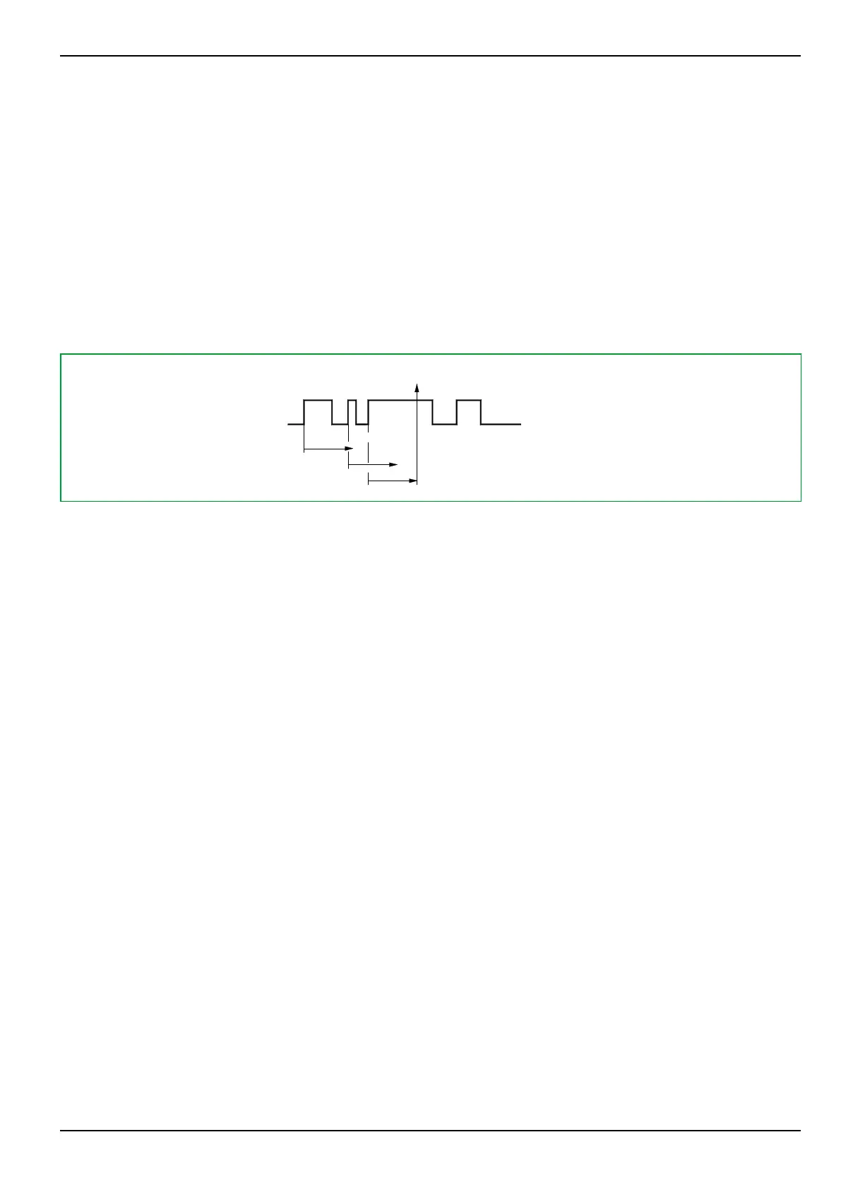
Fig. 3-183: Debouncing signal flow. Set debouncing time: 50 ms.
The first positive pulse edge of the binary input signal to be counted will trigger a
timer stage which will continue to run for the set debouncing time period. Each
positive pulse edge during the debouncing time re-triggers the timer stage. The
binary input signal will be counted if it is stable during the set debouncing time
period.
The debouncing time can be set separately for each of the four counters.
After the set debouncing time has elapsed, the state of the signal is checked. If it
is the same as prior to the occurrence of the first pulse edge, it will not be
counted.
3.36.3 Counting Function
The debounced binary signal is counted by a 16 bit counter. The counters may
be set to a specific count value (preload function) by setting a parameter or via
the serial interfaces. The values of the counters can be shown on the LC-display
and read out via the PC interface or the communications interface.
For each of the four counters, there is a limit value that can be optionally set:
●
COUNT: Limit counter 1 (and the same way for counters 2 to 4),
●
settable from 1 to 65000,
●
setting “Blocked” disables the limit check. (This setting is the default
value.)
A warning signal (COUNT: Warning count 1 and the same way for counters 2
to 4) is issued if the associated counter value exceeds the set limit.
3.36.4 Transmitting the Counter Values via Communications Interface
The counter values are transmitted via the communications interface when a
signal is presented to an appropriately configured binary signal input, a trigger
signal is issued by a setting parameter or at cyclic intervals as set at the cycle
time stage COUNT: Cycle t.count transm. When the counter value is
transmitted at cyclic intervals, then transmission is time synchronized if the ratio
3 Operation
P634
P634/EN M/R-42-A // P634‑311‑653 3-227