5.4 Installation
The dimensions and mounting dimensions for surface-mounted cases are given
in Section 4.2, (p. 4-4). When the P634 is surface-mounted on a panel, the wiring
to the P634 is normally run along the front side of the mounting plane. If the
wiring is to be at the back, an opening can be provided above or below the
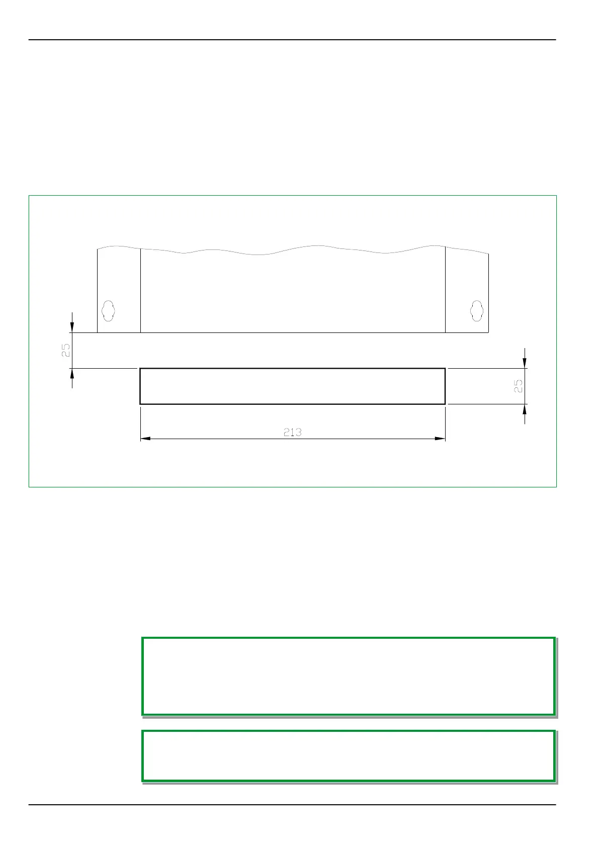
surface-mounted case. Fig. 5-2, (p. 5-6) shows such an opening.
D5Z50MBA
Fig. 5-2: Opening (cutout) for running the connecting leads to an 40 TE surface-mounted case.
The opening width for the 40 TE surface-mounted case: 213 mm (shown in this
figure), for the 84 TE surface-mounted case: 435 mm. The other dimensions are
the same for all cases.
Flush-mounted cases are designed for control panels. The dimensions and
mounting dimensions are given in Chapter “Design”. When the P634 is mounted
on a cabinet door, special sealing measures are necessary to provide the degree
of protection required for the cabinet (IP 51).
Connection of protective grounding conductor: See “Protective and Operational
Grounding” (Section 5.5, (p. 5-12))
Instructions for selecting the flush-mount method:
The P634 has increased mechanical robustness if either the surface-mounted case
or – for the flush-mounted case – flush-mount method 2 (with angle brackets and
frame) is used. In this case, test severity class 2 of the vibration test, test severity
class of the shock resistance test on operability as well as test severity class 1 of
the shock resistance test on permanent shock are applied additionally.
Dimensions of the panel cutouts:
Dimensional drawings of the panel cutouts for all cases and for the detachable HMI
can be found in Section 4.2, (p. 4-4).
P634 5 Installation and Connection
5-6 P634/EN M/R-42-A // P634‑311‑653