Symbol Description
To obtain more space for representing a group of related
elements, contours of the elements may be joined or cascaded if
the following rules are met:
There is no functional linkage between elements whose common
contour line is oriented in the signal flow direction.
Note:
This rule does not necessarily apply to configurations with two or
more signal flow directions, such as for symbols with a control
block and an output block.
There exists at least one logical link between elements whose
common contour line runs perpendicularly to the signal flow
direction.
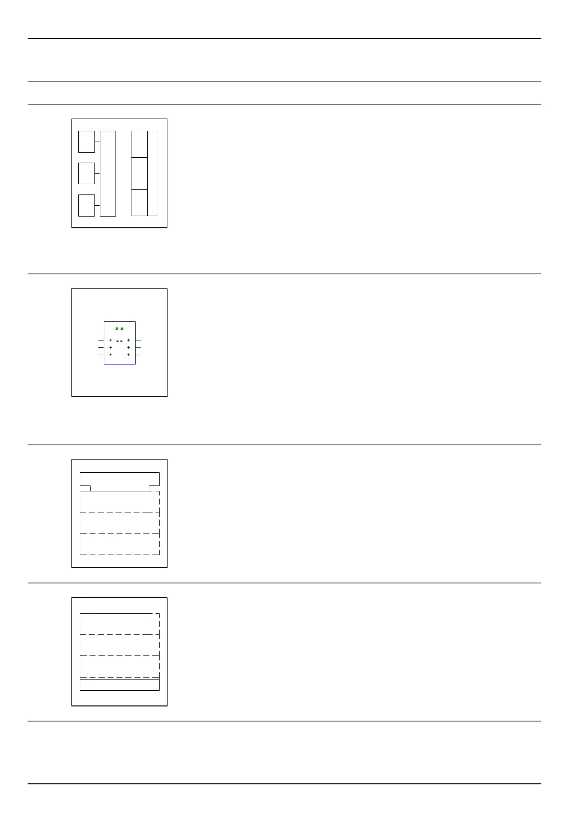
Components of a symbol
A symbol consists of a contour or contour combination and one or
more qualifiers.
Description of the example symbol in the left column
●
Blue line: Contur
●
Dark red lines: Inputs
●
Green lines: Outputs
●
Green hash characters: Preferred location for the general
function qualifying symbol
●
Dark blue asterisk characters: Alternative location for the
general function qualifying symbol
Control block
A control block contains an input function common to several
symbols. It is used for the collective setting of several trigger
elements, for example.
Output block
An output block contains an output function common to several
symbols.
P634 A3 Glossary
A3-2 P634/EN M/R-42-A // P634‑311‑653