Q6Z0116A
REF_1:
Diff. current, REF_1
[ 008 080 ]
REF_1:
Restrain.curr.,REF_1
[ 008 081 ]
REF_1:
Meas. value rel. Id
[ 011 039 ]
REF_1:
Meas. value rel. IR
[ 011 040 ]
REF_1:
Id,N,a
402 550
REF_1:
IR,N,a
402 551
c
c
Fig. 3-104: Measured operating data of differential and restraining currents
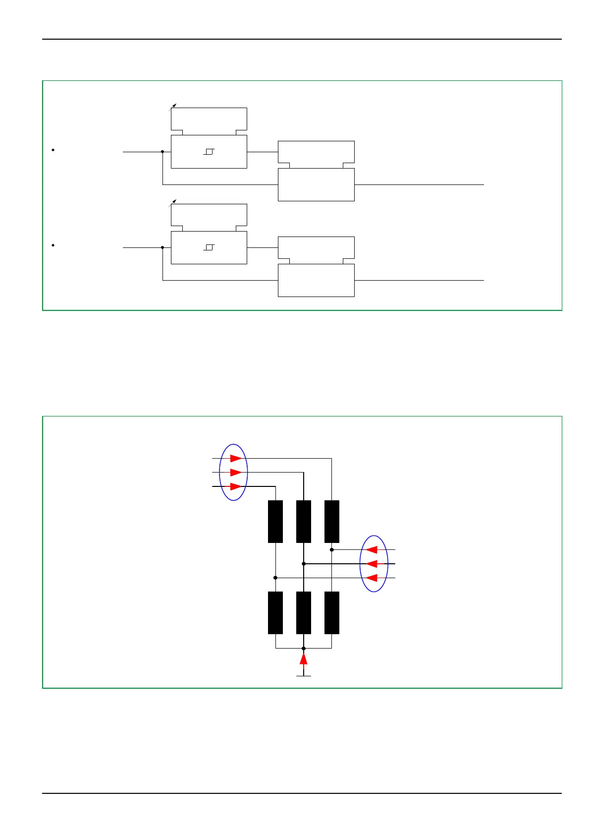
3.22.8 Protection of Autotransformers
Function group REF_1 provides a protection function, stabilized by a
characteristic, for autotransformers; a typical example is displayed in the next
figure. In this case, the phase currents in ends a and b as well as the neutral-
point current must be taken into account.
IA,b
IB,b
IC,b
IA,a
IB,a
IC,a
IY,a
64Z7199B
Σ(Ix,b) = IN,b
Σ(Ix,a) = IN,a
Fig. 3-105: Currents with an autotransformer
For such applications with REF_1, the transformer ends b, c or d may be selected,
and end a is permanently included in the protection function.
(019 120) REF_1: Add.meas.inp. end b = Yes / No (default setting is “No”)
(019 121) REF_1: Add.meas.inp. end c = Yes / No (default setting is “No”)
(019 122) REF_1: Add.meas.inp. end d = Yes / No (default setting is “No”)
3 Operation
P634
P634/EN M/R-42-A // P634‑311‑653 3-149