D5Z08XVB
TXD
RXD
0V
+12V
−12V
V24
9
1
5
3
2
PC interface
with pin connections
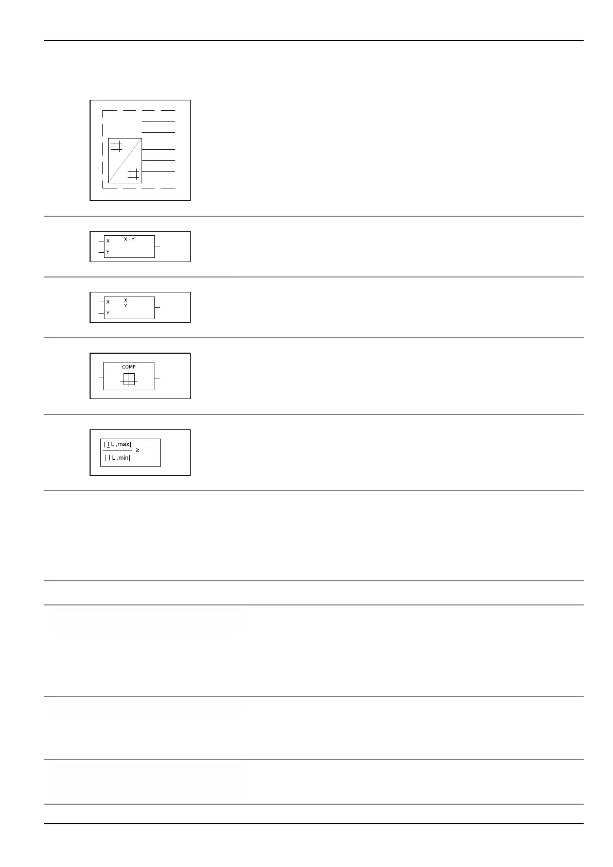
Multiplier
The output variable is the result of the multiplication of the two
input variables.
Divider
The output variable is the result of the division of the two input
variables.
Comparator
The output variable becomes 1 only if the input variable(s) are
equal to the function in the function block.
Formula block
The output variable becomes 1 only if the input variable(s) satisfy
the equation in the function block
Examples of Signal Names
All settings and signals relevant for protection are shown in the block diagrams of
Chapter “Operation” as follows:
Signal Name Description
♦ FT_RC: Fault recording n
305 100
Internal signal names are not coded by a data model address.
In the block diagrams they are marked with a diamond. The
small figure underneath the signal name represents a code that
is irrelevant to the user.
The internal signal names used and their origins are listed in
Appendix.
DIST: VNG>> triggered
[ 036 015 ]
Signal names coded by a data model address are represented
by their address (shown in square brackets). Their origin is
given in Chapters “Setting” and “Information and Control
Functions”.
MAIN: General reset USER
[ 003 002 ]
↗1: Execute
A specific setting to be used later on is shown with its signal
name, address, and the setting preceded by the setting arrow.
A3 Glossary P634
P634/EN M/R-42-A // P634‑311‑653 A3-7