5.7 Location and Connection Diagrams
5.7.1 Location Diagrams P634‑410/411
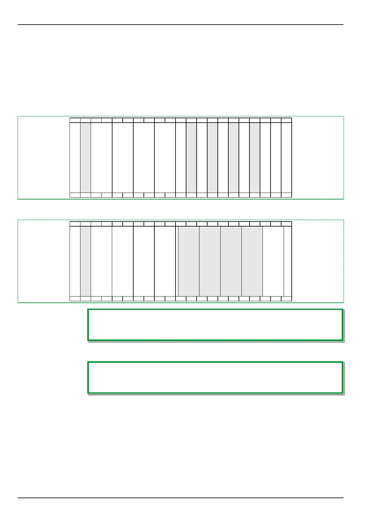
Location diagrams for P634 in 84 TE case
●
Pin-terminal connection (P634 ‑410)
01
01
P
02
02
A
CH1
CH2
A
ETH
CH2
A
Red.
ETH
CH2
03
03
T
4J
1V
04
04
05
05
06
06
07
07
08
08
09
09
T
3I
10
10
11
11
12
12
Y
4I
13
13
14
14
X
24I
15
15
16
16
X
6I
8O
17
17
18
18
X
4H
X
6O
19
19
20
20
V
4I
8O
21
21
T
4J
T
4J
X
6I
3O
●
Ring terminal connection (P634 -411)
01
01
P
02
02
A
CH1
CH2
A
ETH
CH2
A
Red.
ETH
CH2
03
03
T
4J
1V
04
04
05
05
06
06
07
07
08
08
09
09
T
3I
10
10
11
11
12
12
Y
4I
13
13
14
14
X
24I
15
15
16
16
X
6I
8O
17
17
18
18
X
4H
X
6O
19
19
20
20
V
4I
8O
21
21
T
4J
T
4J
X
6I
3O
Each of the numbered slots can be fitted with max. 1 module.
If a location diagram shows several modules for a particular slot, then these are
alternatives, depending on the ordering options.
5.7.2 Terminal Connection Diagrams P634‑410/411
“_” is a placeholder for the slot.
See also Section 5.5, (p. 5-12), “Protection Conductor Terminal (PCT) / Case
Grounding / Protective Earth”
P634 5 Installation and Connection
5-22 P634/EN M/R-42-A // P634‑311‑653