5.6.3.3 Redundant Ethernet Board Connection
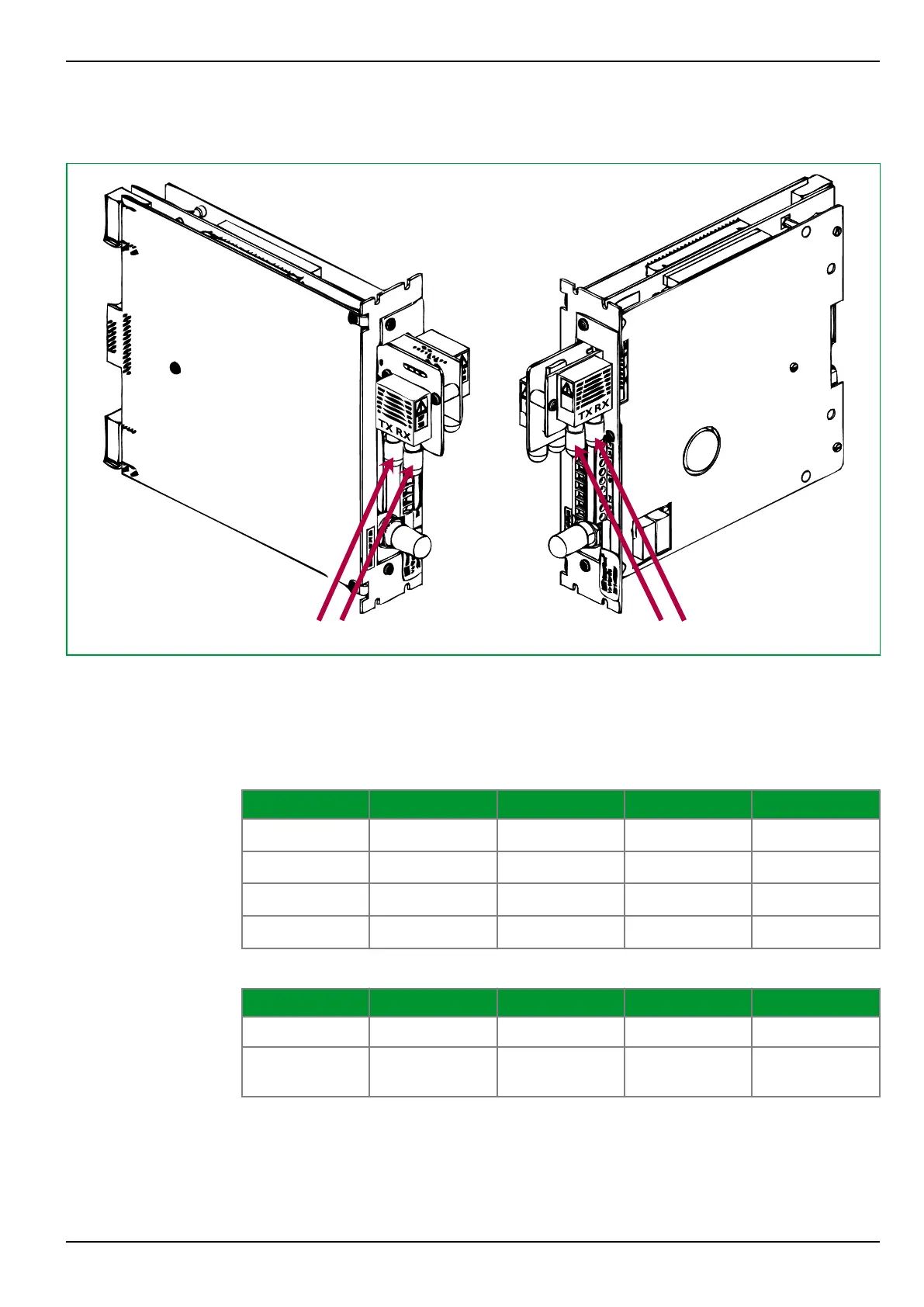
Fig. 5-15: Redundant Ethernet Board connectors.
The diagram above and the related tables below show the global Interface
arrangement of all board connectors, as they are the fiber optic connectors, the
serial interface and the watchdog relay contacts. The available IRIG‑B connector
is designed as a modulated input.
Connector SHP RSTP DHP PRP
A (‑X8)
E
S
T
X1
T
XA
T
XA
B (‑X7)
R
P
R
X1
R
XA
R
XA
C (‑X14)
R
S
R
X2
R
XB
R
XB
D (‑X15)
E
P
T
X2
T
XB
T
XB
Tab. 5-1: Optical fiber connector functionality.
LED Function On Off Flashing
Green Link Link o.k. Link broken
Yellow Activity SHP running
PRP / RSTP or
DHP traffic
Tab. 5-2: LED functionality.
5 Installation and Connection
P634
P634/EN M/R-42-A // P634‑311‑653 5-21