I
d
I
ref
=
I
diff >
I
ref
Characteristics equation for the range 0.5I
diff >
< I
R
≤ I
R,m
2
:
I
d
I
ref
= m
1
⋅
I
R
I
ref
+
I
diff >
I
ref
⋅
(
1 − 0.5 ⋅ m
1
)
Characteristics equation for the range I
R,m
2
< I
R
:
I
d
I
ref
= m
2
⋅
I
R
I
ref
+
I
diff >
I
ref
⋅
(
1 − 0.5 ⋅ m
1
)
+
I
R,m
2
I
ref
⋅
(
m
1
− m
2
)
I
ref
: reference current
m
1
: gradient of the characteristic in range 0.5I
diff >
< I
R
≤ I
R,m
2
m
2
: gradient of characteristic in range I
R,m
2
< I
R
2
4
6
8
2 4 6 8
I
IIIII
64Z9003A
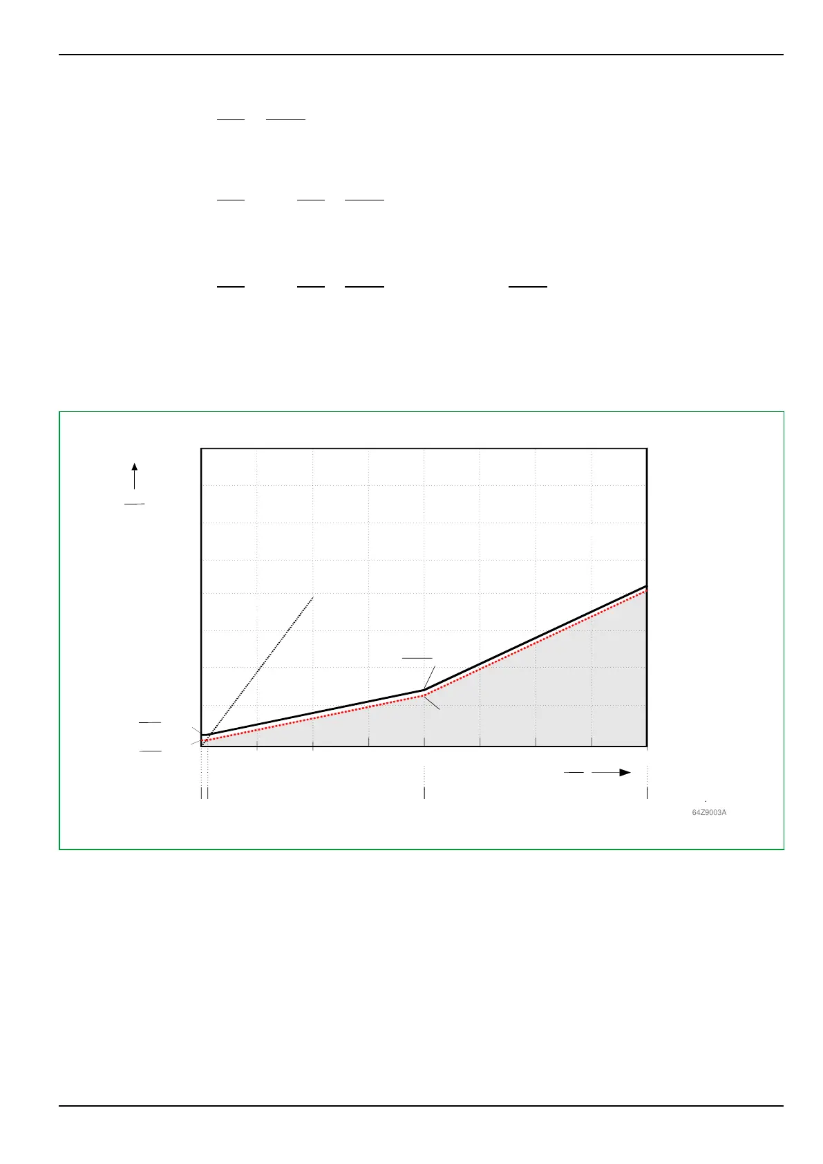
Tripping area
m1 = 0.3
m2 = 0.7
= 0.2
Id>
Iref
IR
Iref
Id
Iref
IR,m2
Iref
= 4.0
Blocking area
Fault current characteristic
for single-side feed
Id>
Iref
* 0.9
Hysteresis active
Fig. 3-91: Tripping characteristic of differential protection
Differential protection can optionally be set to trip with a definite time delay
(setting 010 162 DIFF: Op.del.,trip sig.PSx), used for selectivity between
overlapping differential protection zones. For such applications, also the
hysteresis of the tripping characteristic should be enabled (setting 072 006
DIFF: Hyst. effective PSx = Yes), to avoid chattering operation for faults/test
conditions close to the trip characteristic. Upon differential starting
DIFF: Starting, the hysteresis gets activated, i.e. the basic threshold Idiff> (or
Idiff>(CTS) respectively) is reduced to 90% of the set value. All other
characteristic settings are unchanged. Thus the characteristic is "vertically"
moved towards lower differential current values.
3 Operation
P634
P634/EN M/R-42-A // P634‑311‑653 3-133