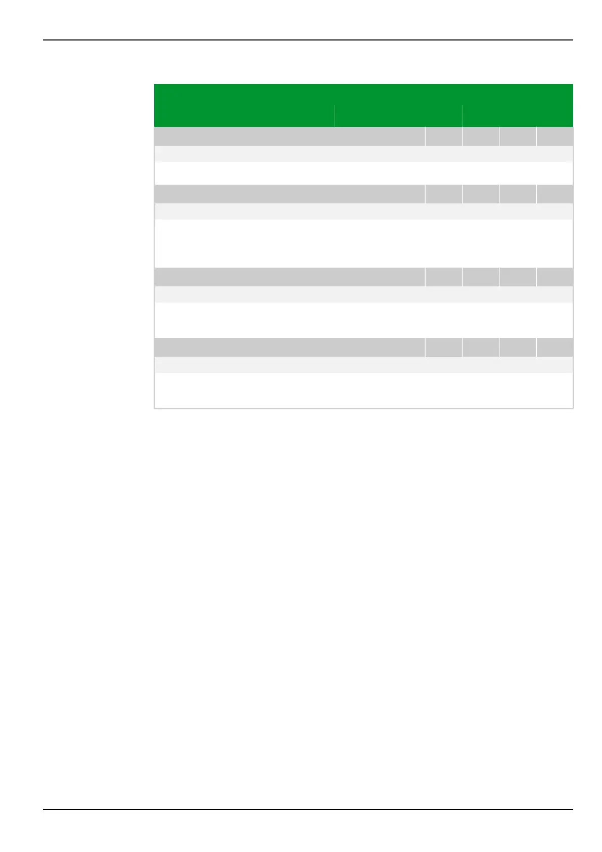
Parameter Address
Default Min Max Unit Logic Diagram
[spacer]
LOC: Fct. Fault Panel
053 003
060 000: MAIN: Without function Fig. 3-3, (p. 3-6)
[spacer]
Definition of the values to be displayed on the Fault Panel.
[spacer]
LOC: Hold-time for Panels
031 075
5 1 10 s Fig. 3-2, (p. 3-5)
[spacer]
Setting for the time period during which a panel is displayed, before switching to
the next panel. This setting is only relevant if more values are selected than can
be shown on the LC-Display.
[spacer]
LOC: Autom. return time
003 014
60 60 60000 s Fig. 3-2, (p. 3-5)
[spacer]
If the user does not press a key on the local control panel during this set time
period, the change-enabling function is deactivated.
[spacer]
LOC: Return time illumin.
003 023
60 60 60000 s
[spacer]
If the user does not press a key on the local control panel during this set time
period, then the backlighting of the LCD display is switched off.
7 Settings P634
P634/EN M/R-42-A // P634‑311‑653 7-13