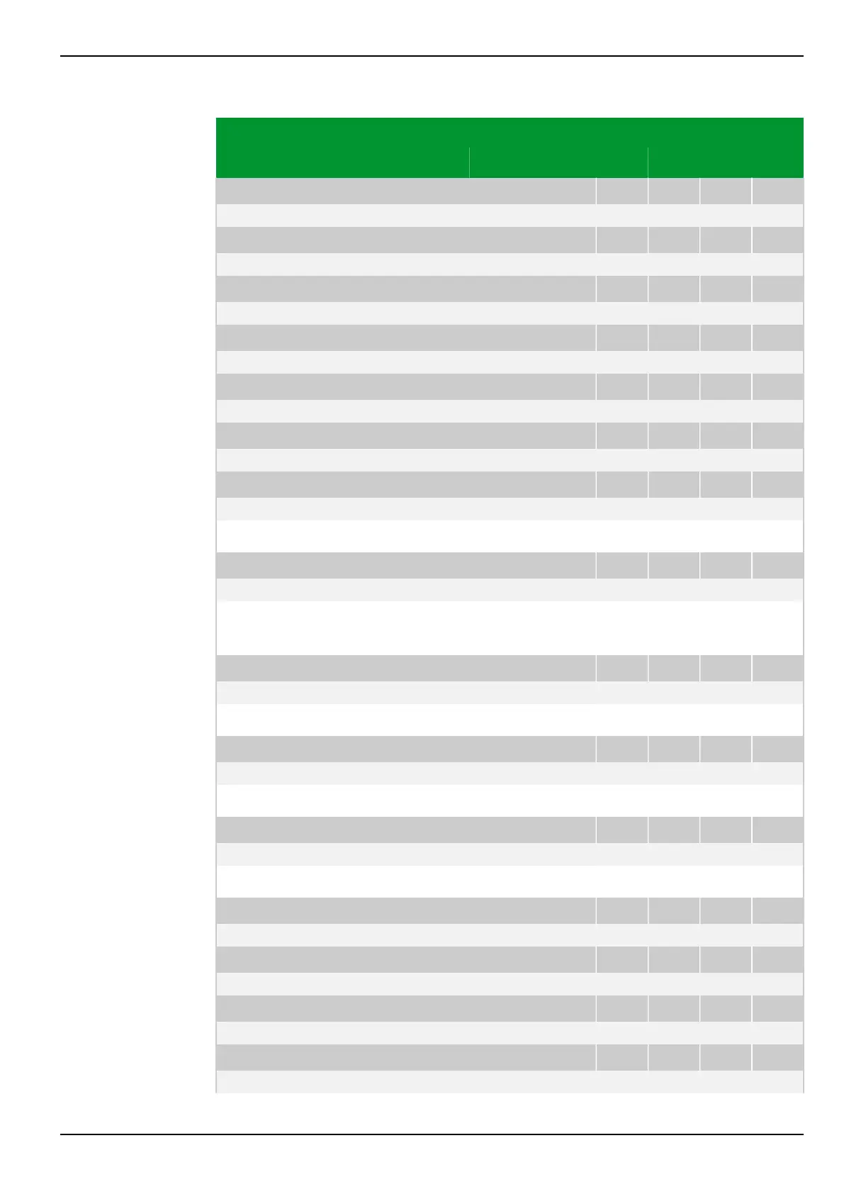
Parameter Address
Default Min Max Unit Logic Diagram
[spacer]
LED: Fct.assig. H20 green
085 167
060 000: MAIN: Without function
[spacer]
LED: Fct.assig. H21 red
085 140
060 000: MAIN: Without function
[spacer]
LED: Fct.assig. H21 green
085 170
060 000: MAIN: Without function
[spacer]
LED: Fct.assig. H22 red
085 143
060 000: MAIN: Without function
[spacer]
LED: Fct.assig. H22 green
085 173
060 000: MAIN: Without function
[spacer]
LED: Fct.assig. H23 red
085 146
060 000: MAIN: Without function
[spacer]
LED: Fct.assig. H23 green
085 177
060 000: MAIN: Without function
[spacer]
Assignment of functions to LED indicators.
[spacer]
LED: Fct.assig. H17 red
085 185
080 111: LOC: Edit mode
[spacer]
Display of the function assigned to LED indicator H 17.
The function LOC: Edit mode is permanently assigned.
[spacer]
LED: Operating mode H 1
085 182
1: ES updating
[spacer]
The operating mode ES updating is permanently assigned.
[spacer]
LED: Operating mode H 2
085 002
1: ES updating
[spacer]
The operating mode ES updating is permanently assigned.
[spacer]
LED: Operating mode H 3
085 005
1: ES updating
[spacer]
The ES updating operating mode is permanently assigned.
[spacer]
LED: Operating mode H 4
085 008
3: ES reset (fault)
[spacer]
LED: Operating mode H 5
085 011
1: ES updating
[spacer]
LED: Operating mode H 6
085 014
1: ES updating
[spacer]
LED: Operating mode H 7
085 017
1: ES updating
7 Settings P634
P634/EN M/R-42-A // P634‑311‑653 7-65