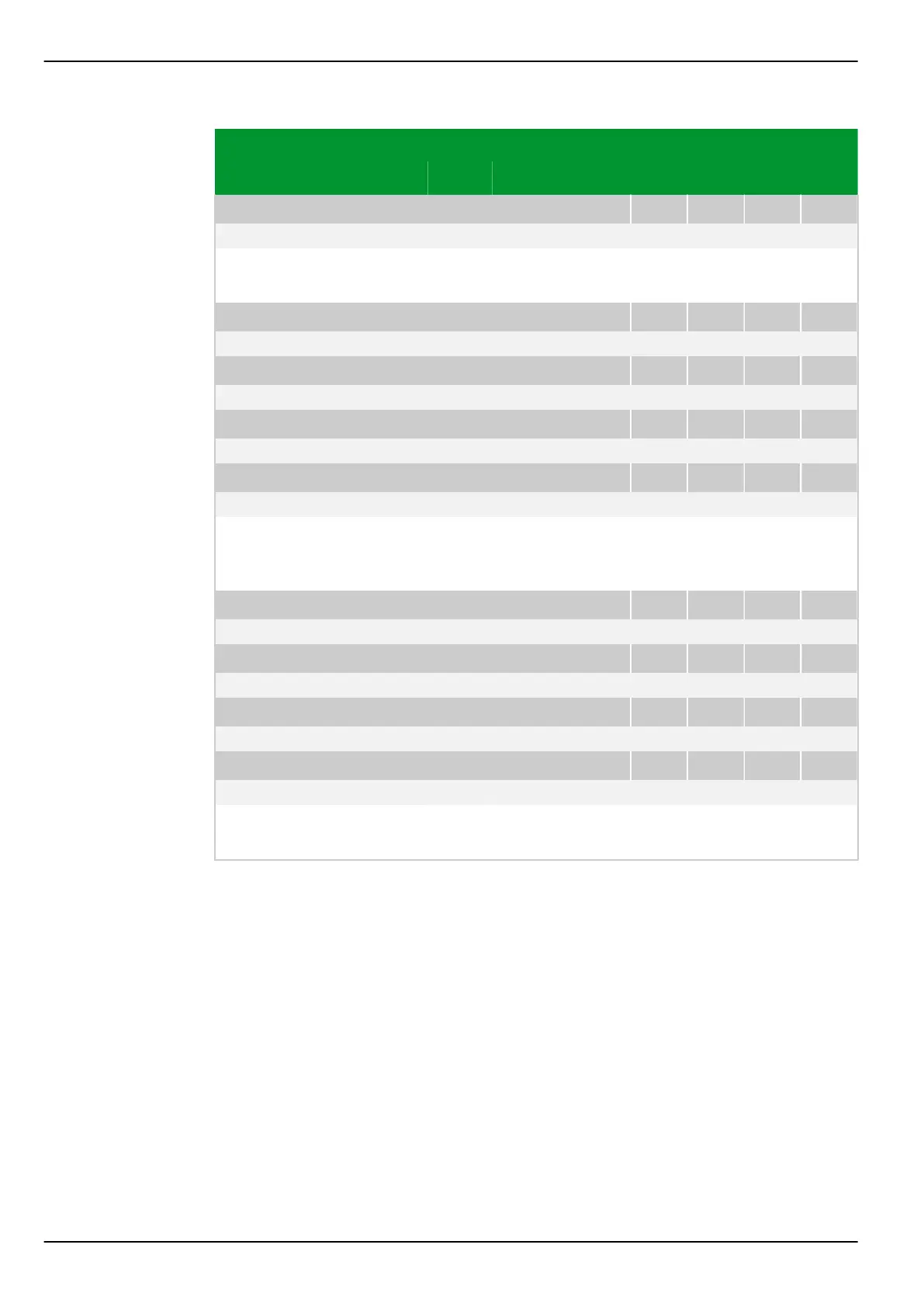
Parameter Address
Default Min Max Unit Logic Diagram
[spacer]
CBF_4: Delay/starting trig.
022 247
0.00 0.00 100.00 s
[spacer]
The signal CBF_1: Trip signal (or CBF_2: Trip signal, . . ., resp.) is
issued when this timer stage's time duration has elapsed.
[spacer]
CBF_1: Delay/fault beh. CB
022 171
0.12 0.00 100.00 s Fig. 3-167, (p. 3-212)
[spacer]
CBF_2: Delay/fault beh. CB
022 227
0.12 0.00 100.00 s
[spacer]
CBF_3: Delay/fault beh. CB
022 240
0.12 0.00 100.00 s
[spacer]
CBF_4: Delay/fault beh. CB
022 254
0.12 0.00 100.00 s
[spacer]
If during this delay time period the circuit breaker does not provide a signal from
its auxiliary contacts that it is closed, then faults behind the CB are recognized
through the current criterion (see section “Fault behind CB protection”).
[spacer]
CBF_1: Delay/CB sync.superv
022 172
Blocked 0.00 100.00 s Fig. 3-168, (p. 3-212)
[spacer]
CBF_2: Delay/CB sync.superv
022 218
Blocked 0.00 100.00 s
[spacer]
CBF_3: Delay/CB sync.superv
022 241
Blocked 0.00 100.00 s
[spacer]
CBF_4: Delay/CB sync.superv
022 255
Blocked 0.00 100.00 s
[spacer]
Setting for the time delay to bridge circuit breaker operate times during CB
synchronization supervision.
P634 7 Settings
7-98 P634/EN M/R-42-A // P634‑311‑653
 Loading...
