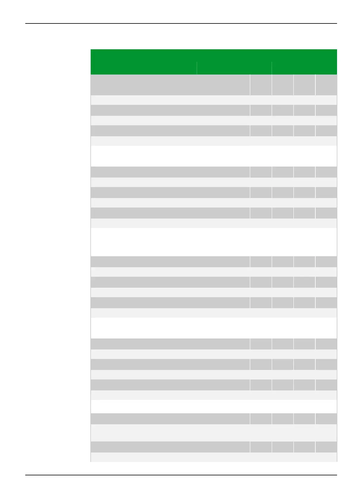
Parameter Address
Default Min Max Unit Logic Diagram
Inverse-time overcur‐
rent protection
IDMT1: Enable PSx
081 050 082 050 083 050 084 050
0: No Fig. 3-116, (p. 3-162)
[spacer]
IDMT2: Enable PSx
081 170 082 170 083 170 084 170
0: No
[spacer]
IDMT3: Enable PSx
081 190 082 190 083 190 084 190
0: No
[spacer]
This setting specifies the parameter subset to be enabled for inverse-time
overcurrent protection.
[spacer]
IDMT1: Block tim.st. IN PSx
081 068 082 068 083 068 084 068
0: Without
[spacer]
IDMT2: Block tim.st. IN PSx
081 188 082 188 083 188 084 188
0: Without
[spacer]
IDMT3: Block tim.st. IN PSx
081 208 082 208 083 208 084 208
0: Without
[spacer]
This setting defines whether a blocking of the residual and negative-sequence
current stages should take place for single-pole startings or multi-pole phase
current startings.
[spacer]
IDMT1: Gen.starting modePSx
081 059 082 059 083 059 084 059
1: With start. IN/Ineg Fig. 3-125, (p. 3-173)
[spacer]
IDMT2: Gen.starting modePSx
081 179 082 179 083 179 084 179
1: With start. IN/Ineg
[spacer]
IDMT3: Gen.starting modePSx
081 199 082 199 083 199 084 199
1: With start. IN/Ineg
[spacer]
This setting defines whether starting of the residual current stages will result in
the formation of the general starting signal of IDMT protection.
[spacer]
IDMT1: tGS PSx
081 058 082 058 083 058 084 058
0.00 0.00 100.00 s Fig. 3-125, (p. 3-173)
[spacer]
IDMT2: tGS PSx
081 178 082 178 083 178 084 178
0.00 0.00 100.00 s
[spacer]
IDMT3: tGS PSx
081 198 082 198 083 198 084 198
0.00 0.00 100.00 s
[spacer]
Setting for the operate delay of the general starting signal of IDMT protection.
[spacer]
IDMT1: Rush restr.enabl PSx
081 060 082 060 083 060 084 060
0: No Fig. 3-121, (p. 3-167)
Fig. 3-122, (p. 3-169)
[spacer]
IDMT2: Rush restr.enabl PSx
081 180 082 180 083 180 084 180
0: No
7 Settings P634
P634/EN M/R-42-A // P634‑311‑653 7-167
 Loading...
